14
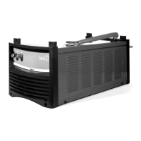
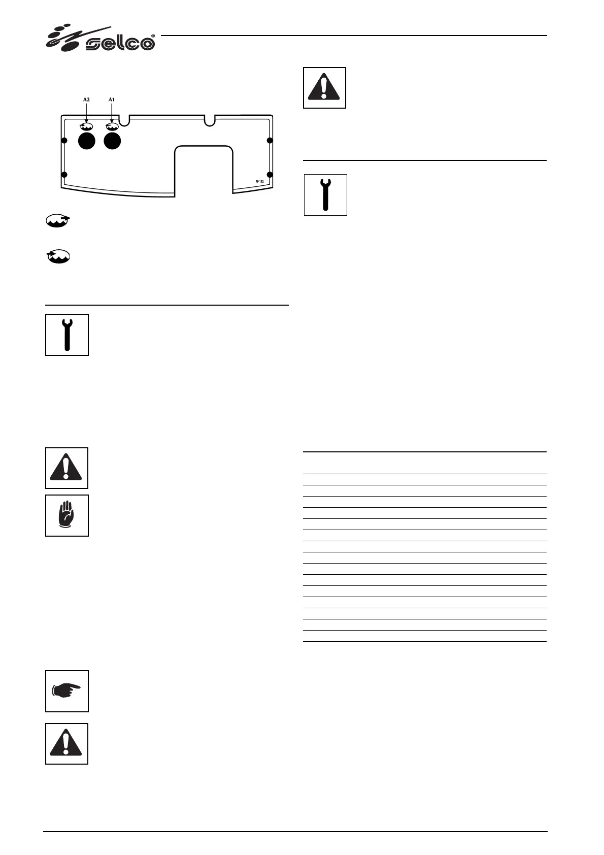
3.2 Rear panel
A1: cooling liquid outlet connector.
To supply low temperature liquid into the torch cooling
circuit.
A2: cooling liquid inlet connector.
To return the liquid that has been heated by the torch
into the cooling circuit inside the WU.
4 MAINTENANCE
Routine maintenance must be carried out on the
system according to the manufacturer’s directives.
Any maintenance operation must be performed by qualified
personnel only.
When the equipment is working, all the access and operating
doors and covers must be closed and locked.
Unauthorized changes to the system are strictly forbidden.
Prevent conductive dust from accumulating near the louvers
and over them.
Disconnect the power supply before every
operation!
Periodically check the cooling liquid level in the
tank. If the tank is completely empty and/or there
is air in the cooling circuit, this may cause mal-
functions of the pump.
- Check the quantity of liquid in the tank (2/3 water and 1/3
antifreeze liquid).
- Clean the unit inside by means of low-
pressure compressed air and soft bristel brushes.
- Check the electric connections and all the connection
cables.
- Check the conditions of the electric pump.
- Check the state of the hose connections.
Every six months, change the cooling liquid and wash out the
hoses and tank with water. Change the liquid in the case where
it should boil, since it would loose its protective properties.
Filling or topping up of the tank with cooling
liquid must be performed with the power source
and WU assembled and positioned on a horizon-
tal surface.
Filling or topping up of the tank must be per-
formed with cooling liquid, code 18.91.001.
The equipment must not be used without cool-
ing liquid.
Do not use conductive cooling liquids.
Missing the above named maintenance will invalidate all
warranties and exempt the manufacturer from all liability.
5 TROUBLESHOOTING
The repair or replacement of any parts in the
system must be carried out only by qualified
personnel.
The repair or replacement of any parts in the system by
authorized personnel shall cause the product warranty to
become null and void.
The system must not be modified in any way.
The manufacturer declines any responsibility in case the user
not follow these instructions.
No liquid flow in circuit
Cause Pump blocked.
Solution With the tank filled and power source off, open the
unit right-hand side cover by unscrewing the two
screws at the bottom.
Partially unscrew the screw valve.
Wait for a few seconds, close the valve and the side
cover and restart the power source.
Cause No liquid in the tank.
Solution Refill.
6 TECHNICAL SPECIFICATIONS
WU21
Power supply voltage U1 (50/60Hz) 1x400V
Input current I1 0.6A
Cooling power (25°C) 1.9 kW
Type of exchanger H2O - Air
Nominal flow rate 1.4 l/min
Total head 35 m
Pump type Centrifugal
Maximum No. of revolutions 2850/3300 No/min
Protection rating IP IP23S
Insulation class F
Tank capacity 6 l
Normative references EN 60974-2/EN 60974-10
Dimensions (lxdxh) 660x250x280 mm
Weight 16 Kg.