SELECT GATE SG-1A V1.X INSTALLATION AND USER GUIDE
8
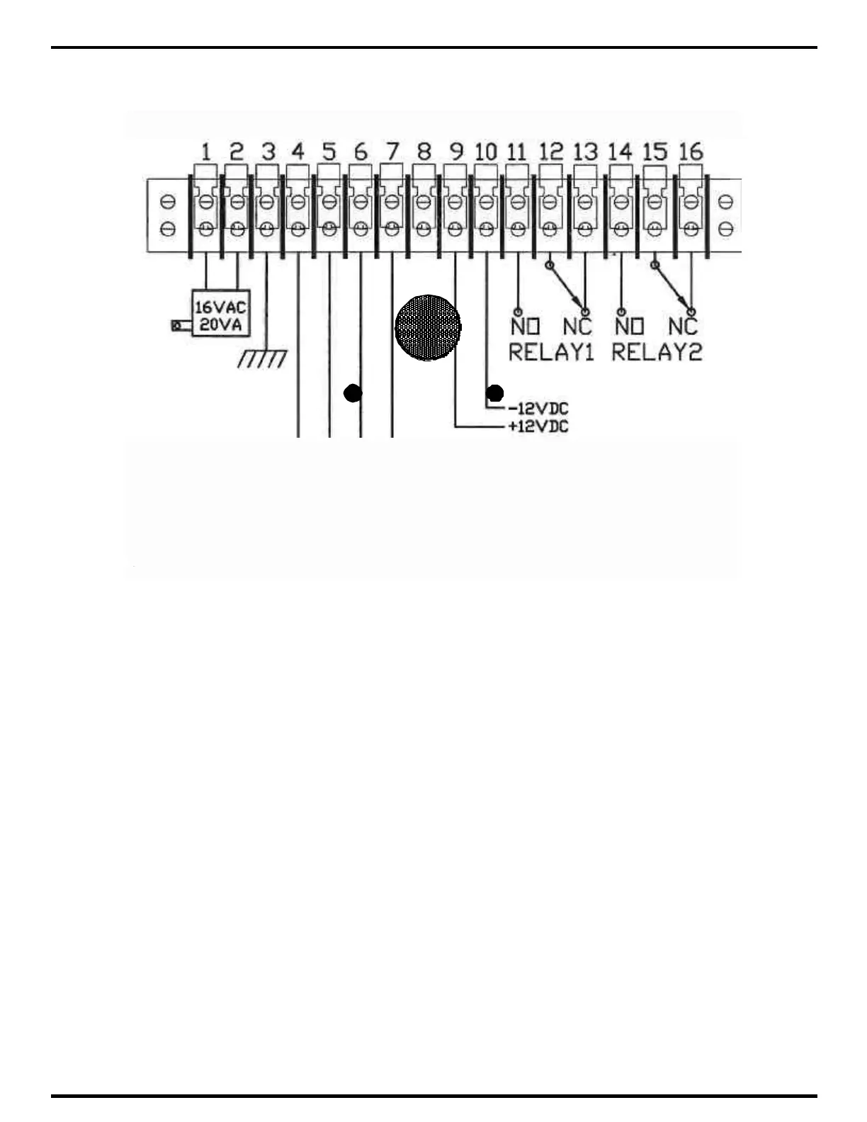
GROUND WITH
# 16 GAUGE WIRE
OR LARGER FOR
BUILDINGS
GROUND WITH
# 14 GAUGE WIRE
OR LARGER FOR
PEDESTALS
3.1.2 GROUNDING SELECT GATE
1) The Select Gate MUST BE AT EARTH GROUND POTENTIAL. Connect a #16 or larger
wire to the ¼ - 20 ground lug mounted on the back-box of the Select Gate. This is immediately to
the left of the terminal barrier strip. Connect the other end of the ground wire to a cold water pipe
or other suitable earth ground. This wire should be less than 50 feet in length.
2) If a cold water ground is not available or located within a reasonable distance, a ground rod will
have to be installed adjacent to the Select Gate installation. Install the ground rod according to
local electrical code requirements. Surge damage protection built into Select Gate is diminished
if adequate earth ground is not provided.
3) If the Select Gate is mounted on a pedestal, a ground rod MUST be installed adjacent to the
Select Gate installation. For pedestal installations using a ground rod, # 14 ga. or larger is
recommended from the ¼ - 20 ground lug mounted on the back-box of the Select Gate to the
ground rod clamp.