SELECT GATE SG-1A V1.X
SELECT ENGINEERED SYSTEMS 11/01 13
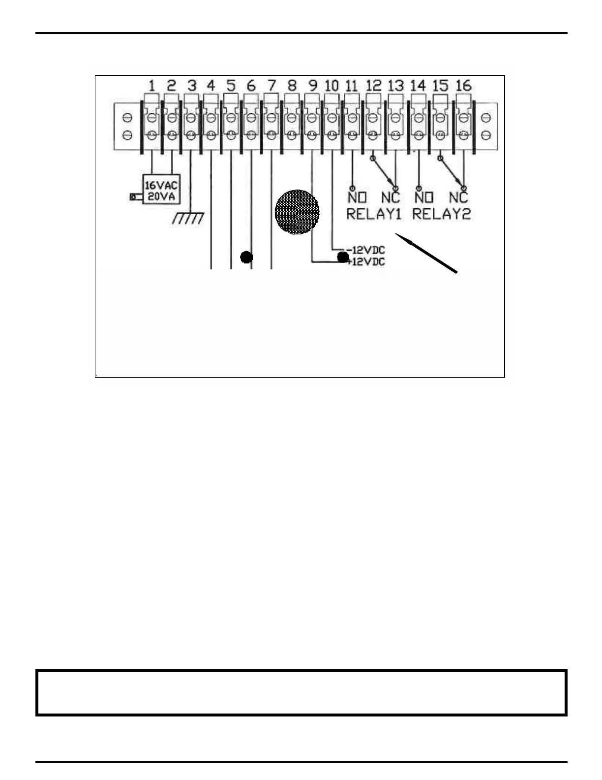
RELAY CONTROL CONTACTS
3.1.5 CONNECTING DEVICES TO CONTROL RELAY
1) If you are using the N.O. contacts on Relay 1, connect the wires from the controlled device to
TBS-11 and TBS-12, as shown above. To use the N.C. contacts, connect the wires from the
controlled device to TBS-12 and TBS-13.
2) If you are using the N.O. contacts on Relay 2, connect the wires from the controlled device to
TBS-13 and TBS-14, as shown above. To use the N.C. contacts, connect the wires from the
controlled device to TBS-14 and TBS-15.
3) Remember these are dry contacts only and do not provide any voltage. Devices that require
voltage such as door strikes and magnetic locks will require their own supply voltage, which will
be switched on and off by the Select Gate control relay.
4) Some solid-state gate controllers react to the over-voltage protection devices used on all SES
products. This is a gate controller dependent problem. The symptom is an intermittent gate open
condition, or gate stuck open condition, sometimes occurring after using the latching function. If
this occurs, add an external relay controlled by the Select Gate output relay contacts to your gate
system. This will help isolate the contacts going to your solid state gate controller.
NOTE: THE RELAY CONTACTS ARE RATED FOR 24 VOLTS AC OR DC AT 2
AMPS