SELECT GATE SG-1A V1.X INSTALLATION AND USER GUIDE
12
TO HOUSE PHONES
TO TELCO
CO
8
5
4
1
1
8
TO
ALARM
PANEL
RED
GRN
SLT
BRN
5
4
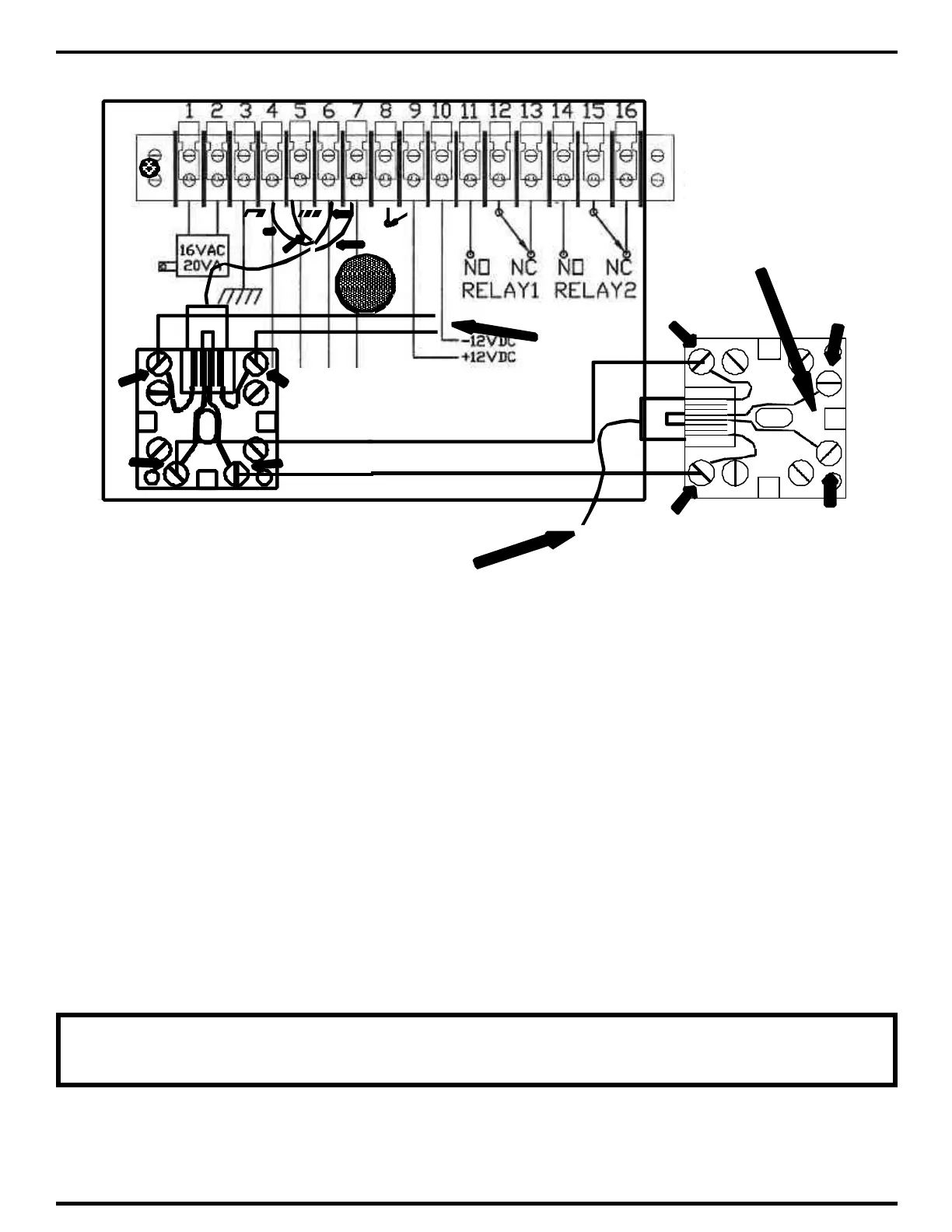
3.1.4.2 CONNECTING SELECT GATE TO HOMES WITH ALARM SYSTEM
1) Connect the Select Gate input to the output of the alarm panel RJ-31X jack as shown above.
This is to ensure that the Select Gate never inadvertently intercepts an alarm signal from the alarm
panel's dialer.
2) Connect terminal 1 from the alarm panel RJ-31X to terminal 4 of the Select Gate -31X jack.
Connect terminal 8 from the alarm panel RJ-31X to terminal 5 of the Select Gate -31X jack.
3) Connect the wires going to the residence (the house phone wiring) to terminals 1 and 8 of the
RJ-31X jack. These wires will be various colors, depending on the manufacturer of the jack.
4) To verify correct connection, remove the Select Gate RJ-31 plug from the Select Gate jack.
Check for continuity from terminal 1 to 4. Next check for continuity from terminal 5 to 8.
5) Plug the RJ-31 plug back into the jack. Next, check for 48 - 52 volts DC across terminals 4 and
5 (this is the telephone dial tone voltage).
NOTE: THE SELECT GATE RJ-31X JACK MUST BE WIRED AFTER ANY
ALARM PANEL OR OTHER SECURITY DIALER