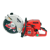
• Remove both attachment nuts (a) entirely.
• Remove the ribbed belt cover (14).
• Put the valve lever (28) for the water supply parallel to
the connection piece so that it does not interfere with the
following work step.
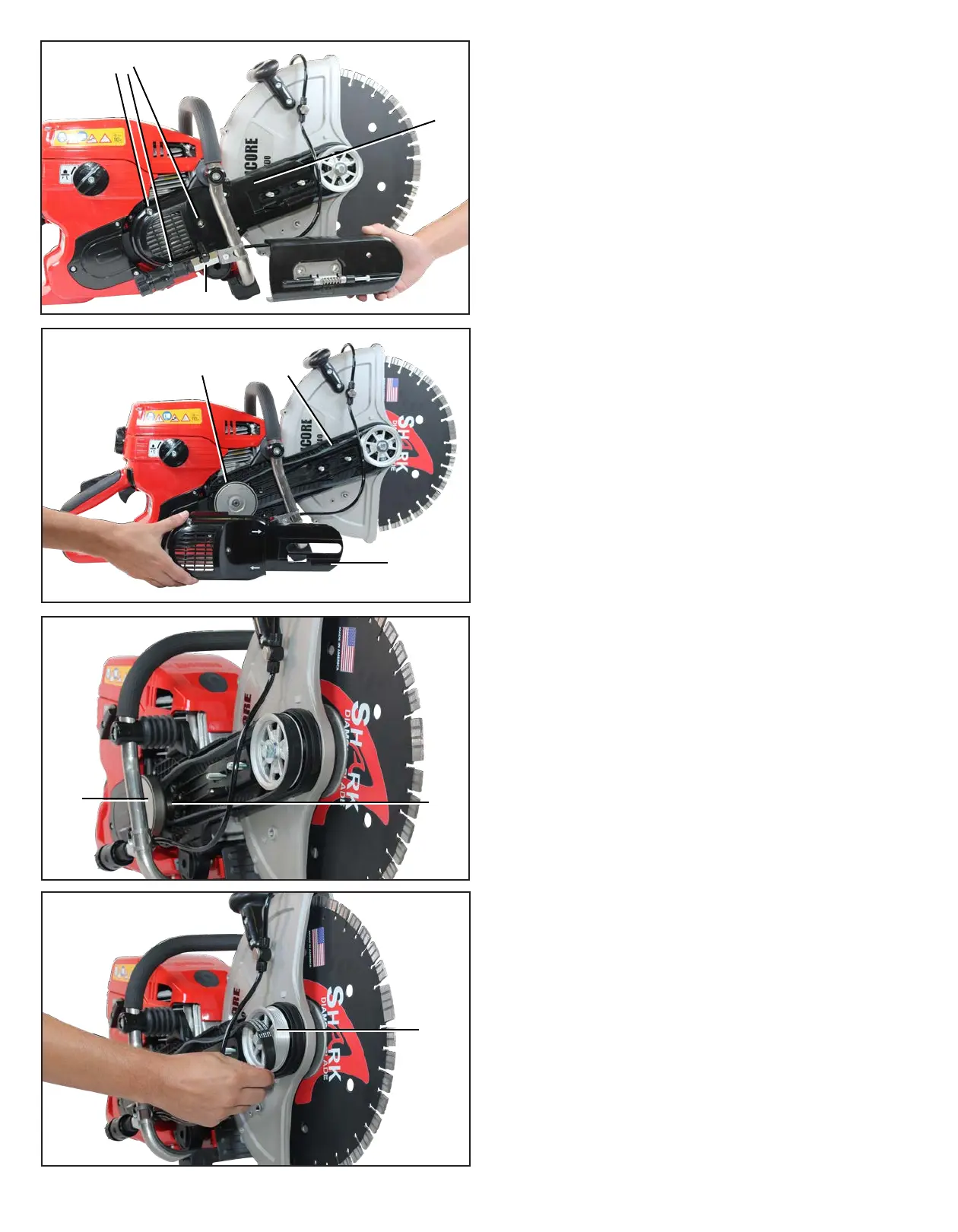
• Remove the coupling cover (e).
• Remove the old ribbed belt (f) or any residue of the old
ribbed belt and any other foreign bodies.
• Use a small brush or paintbrush to clean the open area.
• Place a new ribbed belt on the grooved running surface
(g) on the drive side behind the coupling bell (h).
• Put the other side of the ribbed belt on the grooved
running surface (i) of the ribbed belt support on the output
side.
• Check that the ribbed belt is running freely. Correct
placement of the ribbed belt if required.
• Put on the coupling cover again and check that the
ribbed belt is still running freely. If required, remove the
coupling cover again and correct placement of the ribbed
belt.
• Tighten all 3 attachment screws (d) of the coupling cover
(e) again.
• Check that the ribbed belt is still running freely. If
required, loosen the coupling cover screws again and
correct placement of the ribbed belt.
• Unscrew both attachment nuts (a) of the ribbed belt
• Put on the ribbed belt cover (14) again.
• Screw on both attachment nuts (a) of the ribbed belt
cover again. Only tighten the nuts manually so that the
ribbed belt tension can still be set.
• Turn ribbed belt tension screw (13) towards the right,
e.g. clockwise, to increase the ribbed belt tension). The
correct tension is reached when the square nut (b) is on
thecentermark,i.e.between“+”and“−”.
• Tighten both attachment nuts (a) of the ribbed belt cover.
• Close the water supply valve lever, i.e. put the valve
lever across the connection piece.
e
d
28
e
h
f
h
g
i
32 SENCORE S8100 CUT-OFF SAW MANUAL