EasyManuals Logo

SensorLink Swarm S2 User Manual

Default Icon
42 pages
To Next Page IconTo Next Page
To Previous Page IconTo Previous Page
Page #12 background imageLoading...
Page #12 background image
Doc. No. 702202-252-01 rev. 00
Page 11 of 42
Swarm®S2 Installation and User Manual
Last updated 2021-03-02
by Harald Sleire
© Sensorlink Swarm AS 2021
Step
Description
Illustration
2.
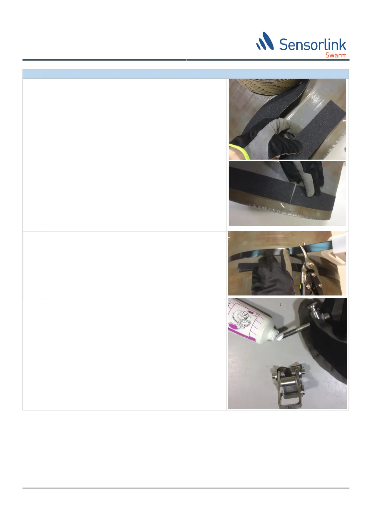
If galvanic separation between the pipe and the PipeMonit®
Swarm® installation is required, tape synthetic galvanic
separation band around the circumference of the pipe before
continuing.
Make sure the galvanic insulation does not cover the TML. The
galvanic insulation shall only be underneath the steel band,
buckle, and sensor brackets.
3.
Place the steel band around the pipe and cut it approximately
100cm longer than the circumference of the pipe on which the
sensors will be installed.
4.
Prepare the buckle by applying the copper paste to the
tightening bolt.

Table of Contents

Questions and Answers:

Question and Answer IconNeed help?

Do you have a question about the SensorLink Swarm S2 and is the answer not in the manual?

SensorLink Swarm S2 Specifications

General IconGeneral
BrandSensorLink
ModelSwarm S2
CategoryMeasuring Instruments
LanguageEnglish

Related product manuals