Doc. No. 702202-252-01 rev. 00
Swarm®S2 Installation and User Manual
© Sensorlink Swarm AS 2021
5.2 The Swarm S2 ultrasound sensor variants
The UT sensors are contact probes with direct contact to the pipe.
Swarm® S2
LT
Ultrasound
Sensor
− Body in aluminium
− Deployment kit in 304SS
− Contain 1 UT sensor + 1 temp sensor.
− Cable: 1-5m standard 4wire cable with
connectors
− Metal loss capability better than
10µm*
− Temperature Range -40°C to +150°C
Swarm® S2
HT
Ultrasound
Sensor
− Body and deployment kit in 304SS
− Delay: line 25mm
− Cable: 300mmMIMS + 2m R316
(variable extensions available)
− SMA Connector
− Metal loss capability better than
20µm*
− Temperature Range +150°C to +380°C
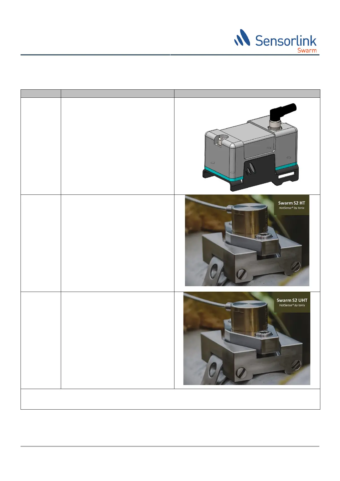
Swarm® S2
UHT
Ultrasound
Sensor
− Body and deployment kit in 304SS
− Delay: line 75mm
− Cable: 300mmMIMS + 2m R316
(variable extensions available)
− SMA Connector
− Metal loss capability better than
30µm*
− Temperature Range +350°C to +550°C
* Metal loss capability is defined as the system’s ability to distinguish wall thickness variations measured at the same location and
temperature over time (repeatability).
Table 4 Swarm S2 Sensor variants