EasyManuals Logo

SensorLink Swarm S2 User Manual

Default Icon
42 pages
To Next Page IconTo Next Page
To Previous Page IconTo Previous Page
Page #32 background imageLoading...
Page #32 background image
Doc. No. 702202-252-01 rev. 00
Page 31 of 42
Swarm®S2 Installation and User Manual
Last updated 2021-03-02
by Harald Sleire
© Sensorlink Swarm AS 2021
The USB port supplies power to S2. When powered from USB, the supply voltage is lower than normal, so the
ultrasound excitation pulse is approx. 20% lower than normal. To achieve full excitation power, it is possible to apply
external power while USB power is connected. This must be done after the USB port is activated.
When connected to the PC the Swarm S2 identifies as a USB serial port, and a virtual COM port is created using
windows Plug’n Play.
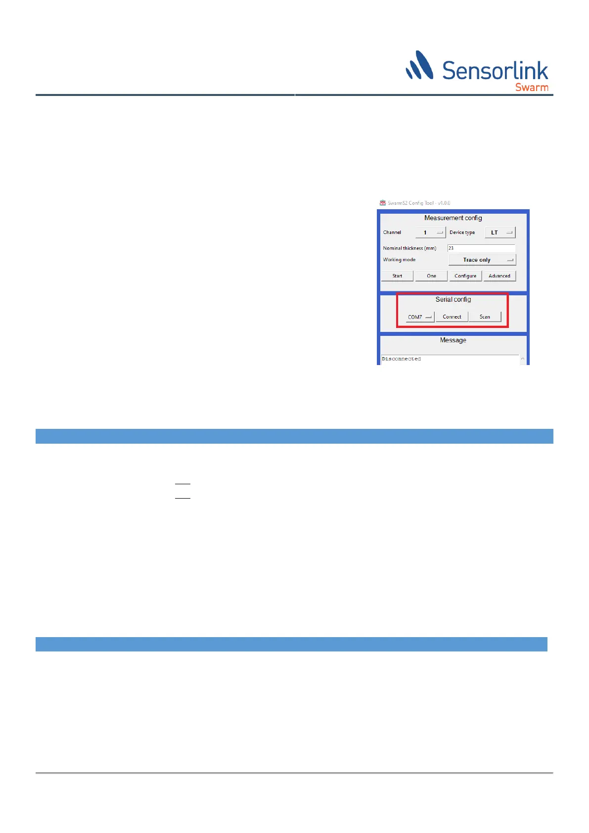
7.2 “Swarm S2 Config Tool”
Connecting the Swarm S2 Config Tool:
1. Start the Swarm S2 config tool application, SwarmS2Config.exe.
2. Click the scan button.
3. Select serial communication port assigned in chapter 7.1.1 or 7.1.2.
4. Click the connect button.
7.3 Micro switches
S2 main board has a micro switch block with 4 switches marked 1 to 4. Normal operation is selected when all
switches are off (up), Figure 12. Other modes are selected like this:
#
Name
Functionality when on (down)
1
Radio off
ISA100.11a radio is disabled, even when lid is equipped with a radio connector.
2
Console
Enables console interpreter. Turn off to enable UltraMonit interpreter.
3
Reserved
Do not turn on (down).
4
Reserved
Do not turn on (down).
7.4 Configuration
In this version of the Swarm S2 Config Tool the number of user adjustable parameters is limited.
7.4.1 Processing parameters
The following user adjustable processing parameters can be entered. The parameter values will be stored in the
instrument.
Name
Description
Auto interval
Minutes between each scheduled measurement. 0 disables scheduled measurements.
Auto offset
Offset of measurements. E.g., to measure every day at 16:00 set log interval to 1440
and log offset to 960.
Nominal wall thickness
Nominal wall thickness used in wall thickness calculations [mm].
No. of channels
Number of transducers connected. 1 to 4 transducers can be connected, and they will
be assigned continuously from 1 to 4.

Table of Contents

Questions and Answers:

Question and Answer IconNeed help?

Do you have a question about the SensorLink Swarm S2 and is the answer not in the manual?

SensorLink Swarm S2 Specifications

General IconGeneral
BrandSensorLink
ModelSwarm S2
CategoryMeasuring Instruments
LanguageEnglish

Related product manuals