© Sensorlink Swarm AS 2021
6.3 Swarm S2 (U)HT Sensor installation
In this section the mechanical installation and electrical connection of the Swarm S2 (U)HT Sensor(s) is explained in
detail. Please note that the HT and UHT sensor is installed in the same manner and sequence, the only difference is
the height of the sensor body, the UHT sensor being 50mm higher than the HT sensor.
6.3.1 Box contents
Swarm S2 (U)HT Sensor(s) comes with the following:
− 1-4 HT or UHT ultrasound sensors as shown in Table 4, these are shipped in individual boxes.
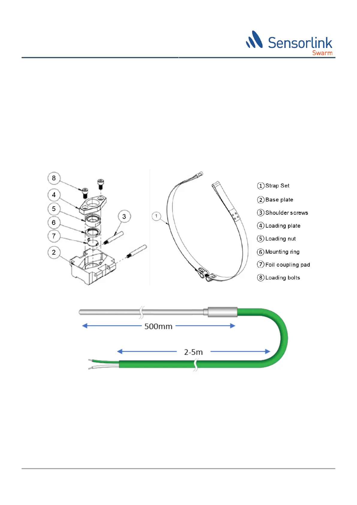
− 1-4 deployment kits, one for each (U)HT sensor, as shown in Figure 3, these are shipped in a separate box.
− 1 K-element temperature probe as shown in Figure 4 is packed in the same box as the deployment kit.
Figure 3 Swarm S2 (U)HT Sensor deployment system (from HotSense® instructions)
Figure 4 Swarm S2 Temperature probe
6.3.2 Required equipment
The following hardware is required for the installation of Swarm S2 (U)HT:
− Sandpaper/machine with 120 to 400 girt.
− 6mm hex key
− Copper paste
− Torque wrench for tightening up to 25Nm
− 6mm hex torque wrench bit