© Sensorlink Swarm AS 2021
6.4.3 Swarm S2 Datalogger(s) mechanical installation
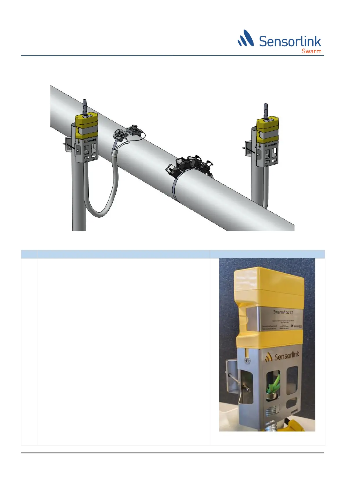
The illustration in Figure 7 gives and overview of typical installation environment for a Swarm S2 system.
Figure 7 Swarm S2 Datalogger installation
Selecting a location for the Swarm S2 Datalogger, please
consider the following:
1) Find a location that is convenient to reach to ease
future battery exchange
2) Find a location with as few metal or concrete obstacles
as possible between the Datalogger and the ISA100
access point (line of sight is prefers for long distances,
>30m)
3) Find a location that limits the heat radiation from hot
pipes to where the Datalogger is located. Use heat
shields if needed
4) If location is exposed to sun and anticipated black bulb
temperature may reach >60-70°C, install a sun shield.
5) A 3” vertical pole should be available at location for
mounting the Datalogger bracket. Make sure the pole
does not run higher than the datalogger body. This is to
avoid shielding the antenna by the pole (may reduce
the radio range of the ISA100 communication).
Please note that the assembly procedure is identical for
Swarm S2 LT and Swarm S2 (U)HT Dataloggers, it is only the
cables and connectors that are different.