Doc. No. 702202-252-01 rev. 00
Swarm®S2 Installation and User Manual
© Sensorlink Swarm AS 2021
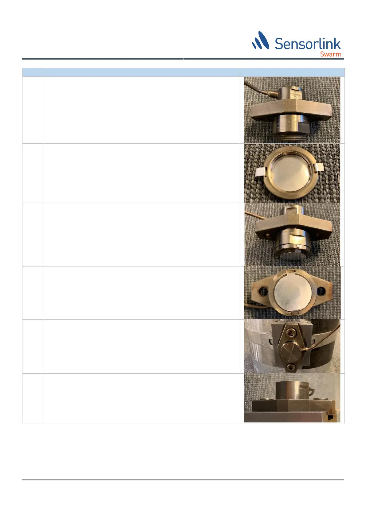
Screw on the loading nut ⑤ to the sensor and tighten by hand.
Carefully bend the tabs of the foil coupling pad ⑦ and insert them
into the holes in the mounting ring ⑥. Push the tabs all the way
through and fold out the tabs down the outside of the mounting
ring. Do not bend or crease the central section of the foil pad.
Screw the mounting ring ⑥ and coupling pad ⑦ onto the sensor
until it is tight against the loading nut ⑥.
The coupling pad ⑦ should be positioned in the centre of the
sensor. Ensure the coupling pad ⑦ is not damaged, creased or
scratched prior to installation.
Position the assembled transducer into the hole in the base plate
② Align the sensor cable in the desired direction ensuring it does
not pass directly over the holes in the loading plate ④. The cable
can be bent to shape, but repeated bending should be avoided.
Insert the loading bolts ⑧ and screw gently by the hex key,
ensuring that the loading plate ④ remains parallel with the base
plate ②.
Check that the loading plate is parallel with the base plate using a
calliper as small misalignment may reduce the performance of the
sensor.