SCORPIO 38’ - 45’ - Crane assembly & transport process - Assembly of the Scorpio 38’-45’
Version 1.02 May 27, 2022
SERVICEVISION BIS SL
Ríos Rosas, 20 · 08940 CORNELLA DE LLOBREGAT (Barcelona) Spain · Tel. 34 93 223 86 30 · Fax 34 93 223 86 31 105
comercial@servicevision.es · www.servicevision.es
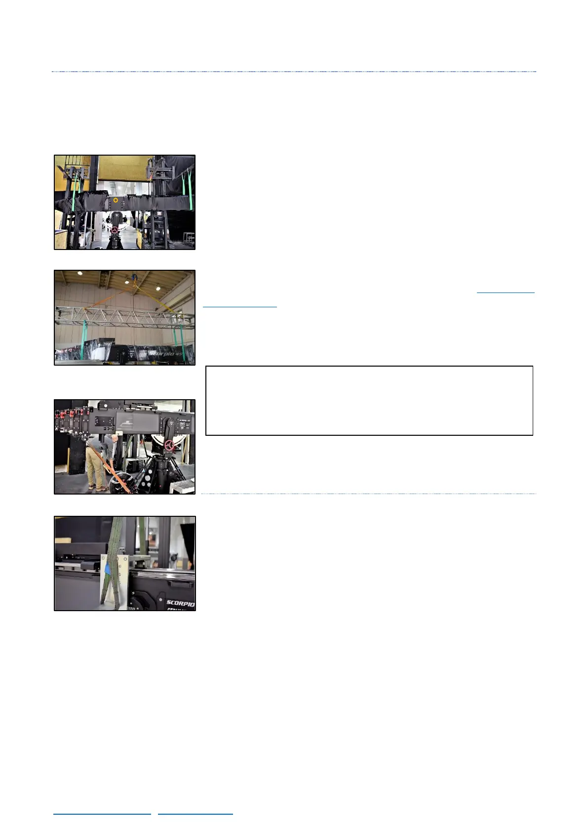
THIRD STEP: THE ARM
For the installation of the arm, it is very important to lift it from the two points marked with the green
straps provided with the crane. The best option is to use two forklifts to ensure that each strap lift the
arm making a U instead of a triangle. If the straps support points are too close, the arm may be
exposed to deformation forces that can lead to malfunction once the crane is assembled.
Once the arm is out of the plywood crate, unwrap the middle part to
slide it into the fulcrum as shown on fig. 10.20.
Notice that there is a set screw in one side of the arm to mark the
position of the arm inside the fulcrum (marked in yellow in fig. 10.20).
Slide the arm inside the fulcrum until the front strap gets loose.
Ensure that the tilt brake is loose and then tight the side screws gently
until all of them are introduced. Once they are all in, start tightening
them in cross until all of them are firm as seen in chapter 2.4
Telescopic arm. Tight both sides equally to prevent the arm to be too
close to one side of the fulcrum.
FOURTH STEP: COUNTERWEIGHTS SUPPORT
To introduce the counterweights support, lift it with the forklift and
prepare it as shown in the fig. 10.23. From this point, just roll the crane
backwards until it can slide between the counterweights motor and the
support where it will lay. Once in the position, remove the strap and
tight it with the twelve screws for it.