SCORPIO 38’ - 45’ - Crane assembly & transport process - Assembly of the Scorpio 38’-45’
Version 1.02 May 27, 2022
106
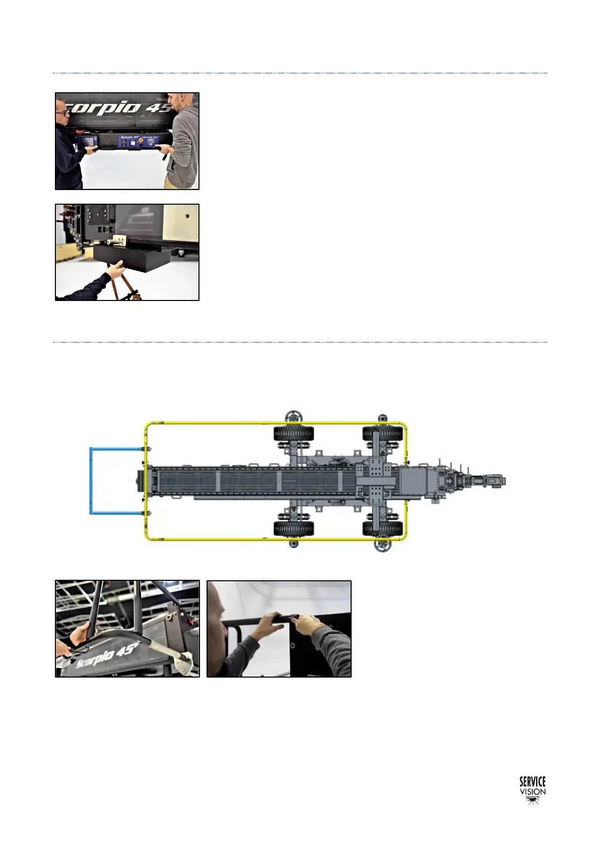
FIFTH STEP: ELECTRONIC BOX AND POWER UNIT
The Electronic box and the power unit for the Scorpio heads are
introduced by sliding them respectively in the back and the front of the
arm. Just remove the stopper screws and slide them in as shown in
the pictures.
Notice that the electronic box is heavy and it is recommended to lift
it between two people.
Once assembled, mount again the stoppers to prevent them to fall
during transport or operation.
SIXTH STEP: PROTECTION BARS
The protection bars (marked as yellow in the picture) are assembled into four pivots in both sides of
the crane and they are tight with Allen screws to hold them in place.
Before introducing them, the bracket
for the hand command needs to be
slide inside the main operation bar
(left or right) since once the bar is
attached, the bracket cannot be
introduced.