SCORPIO 38’ - 45’ - PARTS AND COMPONENTS DESCRIPTION - Column
Version 1.02 May 27, 2022
16
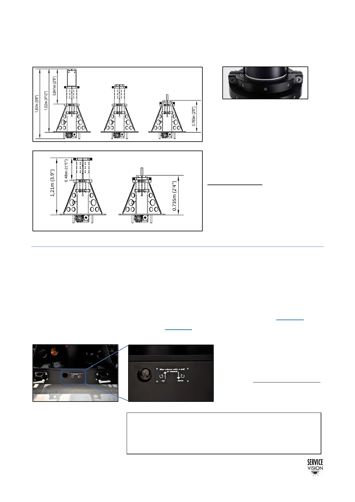
The column of the 45 ‘can be raised up to 84cm / 2’9’’ using both sections, the column of the 38’,
48cm / 1’5”.
There is a white mark in the limit of
each column section so the operator
can visually see when the limit has been
reached and stop telescoping the
column out. Once the desired high is
achieved, remember to lock all the
screws of the column again by tighten
both sides equally. (check the note at
the end of the page)
2.2.2 LIFTING THE COLUMN MANUALLY
Once the column is attached to the dolly there is the possibility to access to the gearbox through the
side of the dolly with the 30mm socket tool, the 2 extenders from the tool kit and the rachet wrench.
It is better to use a drill with the drill adaptor from the accessories. The drill machine needs to be
minimum from 1.5kW of power to be able to lift the column fully loaded.
Move the Counterweights in the middle position as seen on the previous chapter (fig. 02.20). Now
loose the screws from the column to be lifted (fig. 02.21). and use the access in the dolly to introduce
the socket tool and move as labeled to lift or retract the column.
Remember to stop lifting once the
white mark is showed. Once lifted at
the desired high, tight the screws of
the column equally from both sides.
Note: Before lifting the column, balance the arm with the CW
carriage in the center of the column, remove the arm straps,
fix pan and tilt brakes and ensure the column bolts are
loose.