SCORPIO 38’ - 45’ - PARTS AND COMPONENTS DESCRIPTION - Column
Version 1.02 May 27, 2022
SERVICEVISION BIS SL
Ríos Rosas, 20 · 08940 CORNELLA DE LLOBREGAT (Barcelona) Spain · Tel. 34 93 223 86 30 · Fax 34 93 223 86 31 15
comercial@servicevision.es · www.servicevision.es
2.2.1 LIFTING THE COLUMN USING THE HAND COMMAND
To lift the column using the hand command the crane needs to be ON. Once the crane is on, wait
until the dynamic counterweight system calibrates automatically. Then move the arm to one extreme
of it in order to detect the magnetic limit of that extreme (the right procedure is explained in the chapter
3.2 Starting the crane).
Once the main screen is showed, move the counterweight carriage
to the center of the fulcrum using the Hand Command to telescope
the arm. It is important to keep the weight of the crane as close as
possible to the center.
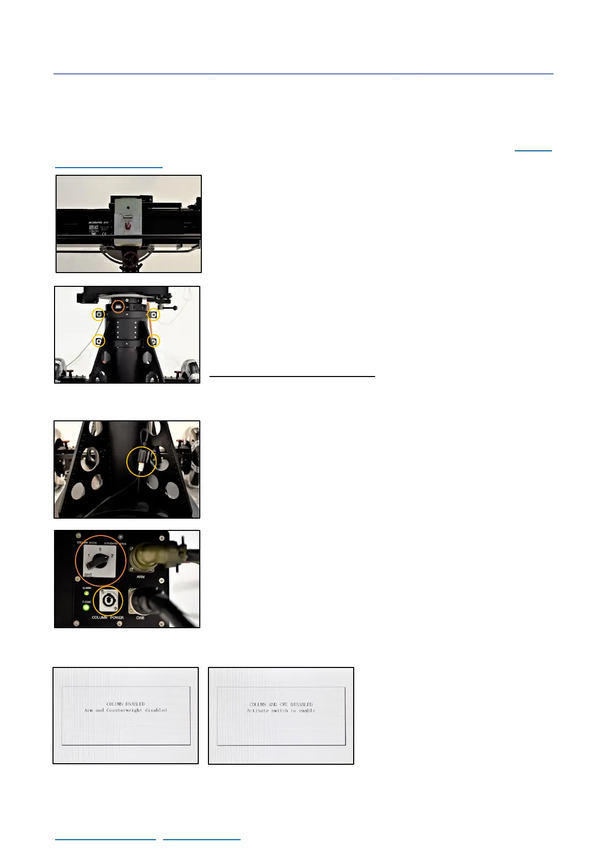
Each section can be raised independently by losing the screws on
the sides of the column sections (fig.02.21). There are 4 screws for
the middle section and 2 for the inner one. Loose them from the nut
(DIN6330 M20) using the socket wrench provided with the crane.
Always lift the middle section first and, in case more high is required,
lift the inside one.
The connector for the column motor is in one side of the column.
Connect the column cable into the column connector and into the
electronic box by sliding it in and twisting it to lock it in place.
Once the cable is connected and the main screen is showed on the
display, change the selector (fig. 02.23) from the standard mode to
the column mode. The display will show that column mode is activated
(fig. 02.24). Then use the cursor from the Hand Command to lift or
lower the column.
In case the selector is in the middle
position, column and counterweights
will be disabled and it will not be
possible to move them until the
selector position changes again.
02.20 Counterweights in the center pos.