SCORPIO 38’ - 45’ - PARTS AND COMPONENTS DESCRIPTION - Leveling head
Version 1.02 May 27, 2022
38
2.7 LEVELING HEAD
The Leveling Head (L.H.) is the component of the crane that holds the horizon when the crane
moves up and down. It has a Mitchell mount in it to mount any kind of head with this mount.
It is located at the end of the telescopic sections. The function of the
leveling head is to hold the horizon vertically. It only corrects the level
in the same direction than the arm. To adjust the lateral level, see the
chapter 2.4.2.4 Fourth Section. There is explained how to lateraly
move the Leveling Head plate by loosing the screws.
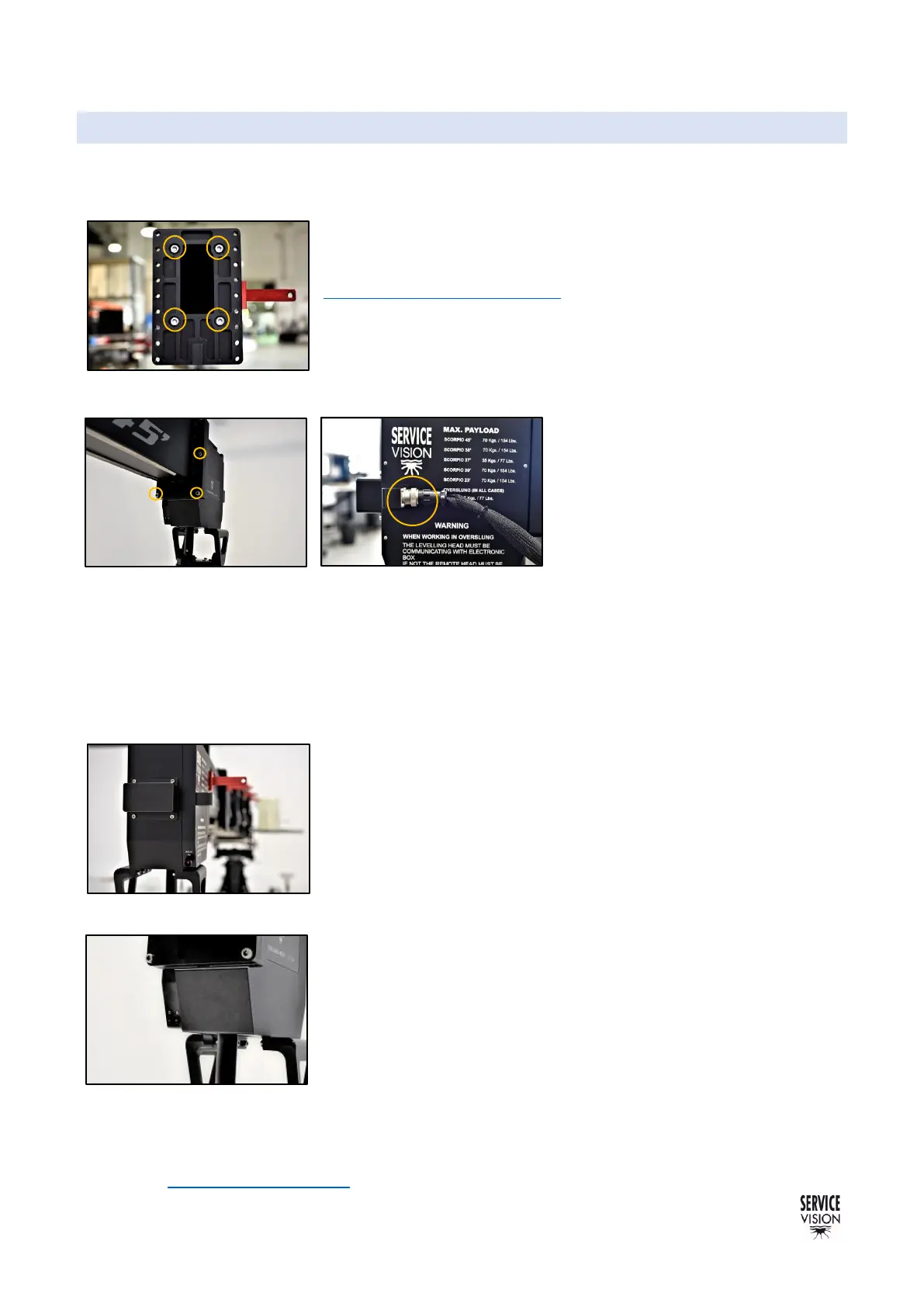
To attach the leveling head into the fourth section there are 6 screws
that attach the LH into the Leveling Head plate (DIN912 M8x35mm).
There are different positions to align the LH into the fourth section.
The leveling head needs to be
connected in order to communicate
with the EB. This kind of connectors
needs to be twisted clockwise from
the metallic part until they are
secured.
In the front part of the leveling head there are 2 components: the inclinometer box and the brake
switch. The inclinometer gives information to the LH about the actual degrees of inclination respect
the horizon. It only uses the inclinometer when is started. Once it finds the level it uses the encoder
on the tilt of the crane to know the change of position. The brake switch is to be able to deactivate the
electro brake that holds the motor in position. The normal position of this switch is ON.
To deactivate this electro brake, change the switch position to OFF
and then start the crane. The LEDs of the LH will be red and the level
of the Mitchell mount can be modified manually.
There are two LEDs in the Leveling Head, S and D:
S LED: This LEDs inform of the status of the SERVO board
controlling the L.H. motor. There are three possible status: OFF
(there is no power in the board), RED (the board has power but no
communication with the CCU) and GREEN (power and
communication arrive to the board).
D LED: This LED indicate the status of the Amplifier of the L.H. motor.
There are three possible status: OFF (there is no power in the
amplifier), RED (the amplifier has power but the motor is disengaged)
and GREEN (the motor is engaged and controlled by the system).
The Leveling Head can be mounted Underslung or Over slung. To
mount it over slung, detach the LH from the crane unscrewing the 6 bolts and mount it with the Mitchell
mount in the upper part of the LH. Then in the Display change the mode of the Leveling Head to Over
slung (see chapter 4.2.3.1 Leveling).