CDHD Product Description
User Manual 13
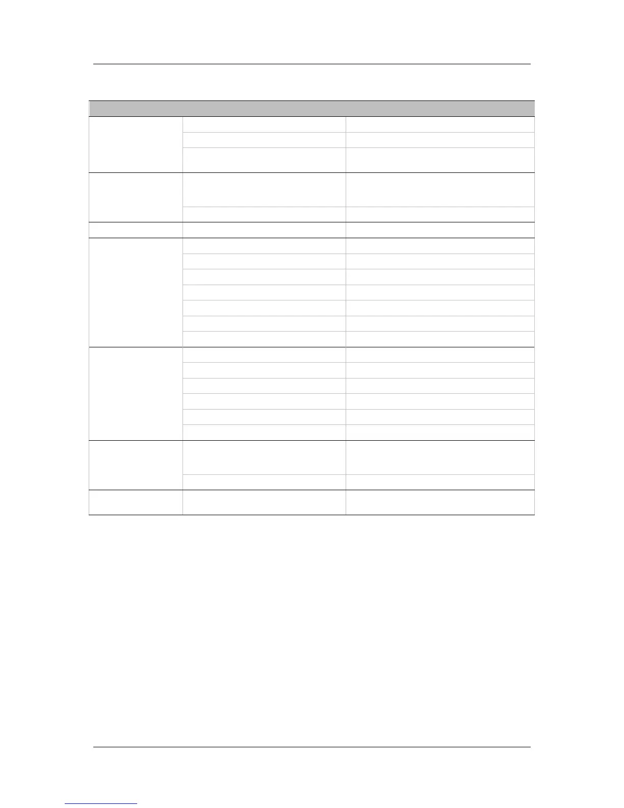
2.2.8 Motor Feedback
Motor Feedback Specification
General Supply Voltage from Drive 5 VDC
Max. Supply Current from Drive 250 mA
Max. Cable Length
AWG 28 – 3 m
AWG 24 – 10 m
Incremental Encoder Signal
A-quad-B with or without marker/Halls,
8-channel Tamagawa, RS 422 or RS485 line
receiver, Differential
Max Input Frequency 3 MHz (before quadrature)
Halls Signal Open collector single-ended
Resolver Signal Sine cosine differential
Transformation Ratio 0.45-1.6
Excitation Frequency 8 kHz
Input Voltage from Drive 6-22 Vpp
Max. DC Resistance 120 Ω (stator)
Max. Drive Current 55 mA rms
Output Voltage to Drive 10 Vpp
Sine encoder Signal Sine/Cosine differential, with or without Halls
Signal Level 1 Vpp @ 2.5 V
Max. Input Frequency 270 kHz
Protocols EnDat
®
2.1, Hiperface
®
Input Impedance 120 Ω
Maximum Drive Internal Interpolation 4096
SSI encoder Signal
Differential data and clock for synchronous
encoders
Data only for asynchronous encoders
Protocols EnDat 2.2, BiSS-C, other SSI
Motor Temperature Signal
Thermal resistor PTC or NTC, User-defined
fault threshold