CDHD Installation
User Manual 27
3. Connect L1C and L2C (for logic power).
If the main voltage is from a single-phase source, connect line and
neutral to L1C and L2C.
If the main voltage is from a three-phase source, connect any two
phases to L1C and L2C.
Make sure the main voltage rating matches the drive specification.
Applying incorrect voltage may cause drive failure.
Do not apply power until all hardware connections are complete.
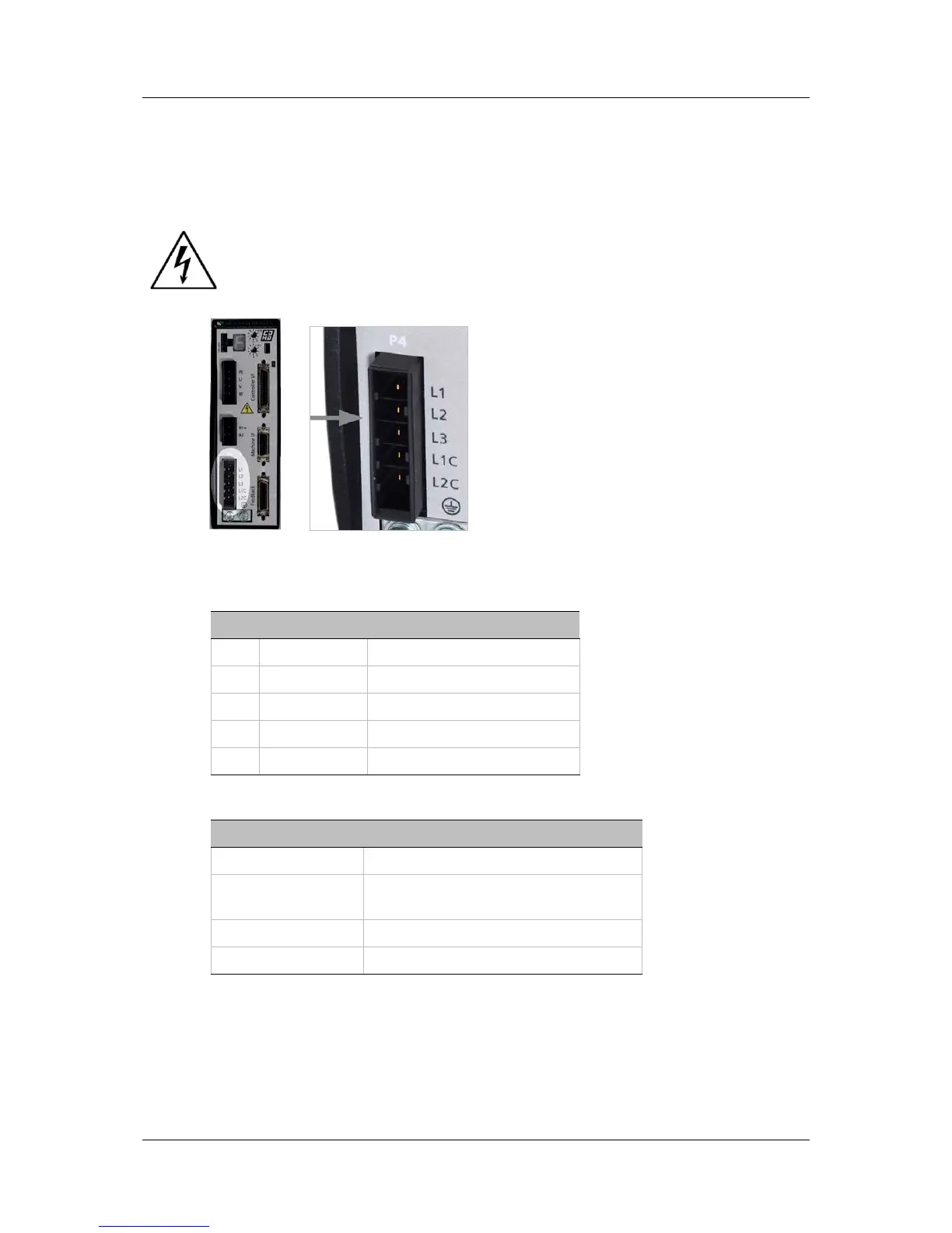
Figure 3-9. AC Input Voltage Interface
Table 3-11. AC Input Voltage Interface
Pin Pin Label Function
1 L1 AC Phase 1
2 L2 AC Phase 2
3 L3 AC Phase 3
4 L1C Logic AC Phase 1
5 LC2 Logic AC Neutral
Table 3-12. AC Input Voltage Interface Mating Connector
Item Specification
Manufacturer JST
Housing and
5-pin crimp
Part # F32FSS05-V-KX and
Part # SF3F71-GF-P0.2
Spring terminal Part # 05JFAT-SAYGF-I
Wire Gauge 14–16 AWG
3.5 Set the Drive Address
The CDHD has two 10-pole rotary switches, accessible from the front of the unit.
The switches are used to set the drive address. When there is more than one
drive on a daisy-chain or CANbus network, each drive must have a unique
address to enable its identification on the network.