CDHD Installation
User Manual 25
Pin Function Description Pin Function Description
9
Direction
input+
High side of the direction
signal (RS422)
27
Direction
input-
Low side of the direction
signal (RS422)
10 Ground Digital ground 28 Pulse input+
High side of the pulse
signal (RS422)
11 Pulse input-
Low side of the pulse signal
(RS422)
29 Ground Digital ground
12 Reserved for future use 30 Reserved for future use
13 Ground Digital ground 31 Digital input 3
Opto-isolated
programmable digital
input. Read using IN3
14 Digital input 4
Opto-isolated
programmable digital input.
Read using IN4
32 Digital input 5
Fast opto-isolated
programmable digital
input. Read using IN5
15 Digital input 6
Fast opto-isolated
programmable digital input.
Read using IN6
33
Digital
output 2
Opto-isolated
programmable digital
output. Read using OUT2
16
Digital
output 3
Fast opto-isolated
programmable digital
output. Read using OUT3
34 Reserved for future use
17 Reserved for future use 35*
Analog
input 2+
High side of the second
differential analog input
(±10 VDC)
36 Analog output
Analog output, referenced
to digital ground (0-10
VDC)
* Optional, see ordering information
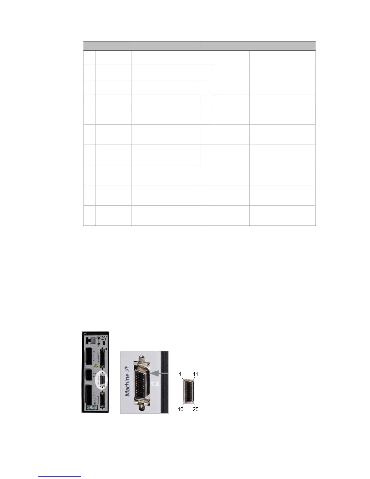
3.4.6 Connect Machine I/Os (C3)
Wire the machine inputs and outputs according to the requirements of your
application.
Unused pins must remain unwired.
To preserve isolation of the digital I/Os, connect a 24 VDC source to pin 9.
Connect the return of the 24 VDC supply to pin 19, which functions as the
ground path for the outputs.
Note: The 24 VDC supply and return can be connected on either the Controller
interface (C2) or the Machine interface (C3), but it is not necessary to
connect it to both.
Figure 3-7. Machine I/O Interface