Configuration and Operation CDHD
32 Servotronix
Remote (Hardware) Enable
This is a signal in the range of 5—24 VDC that is applied to one of the opto-
isolated digital inputs in the Controller I/O connector.
The input must be configured for use as the Remote (Hardware) Enable
input, using INMODE.
The state of the signal can be read, using REMOTE.
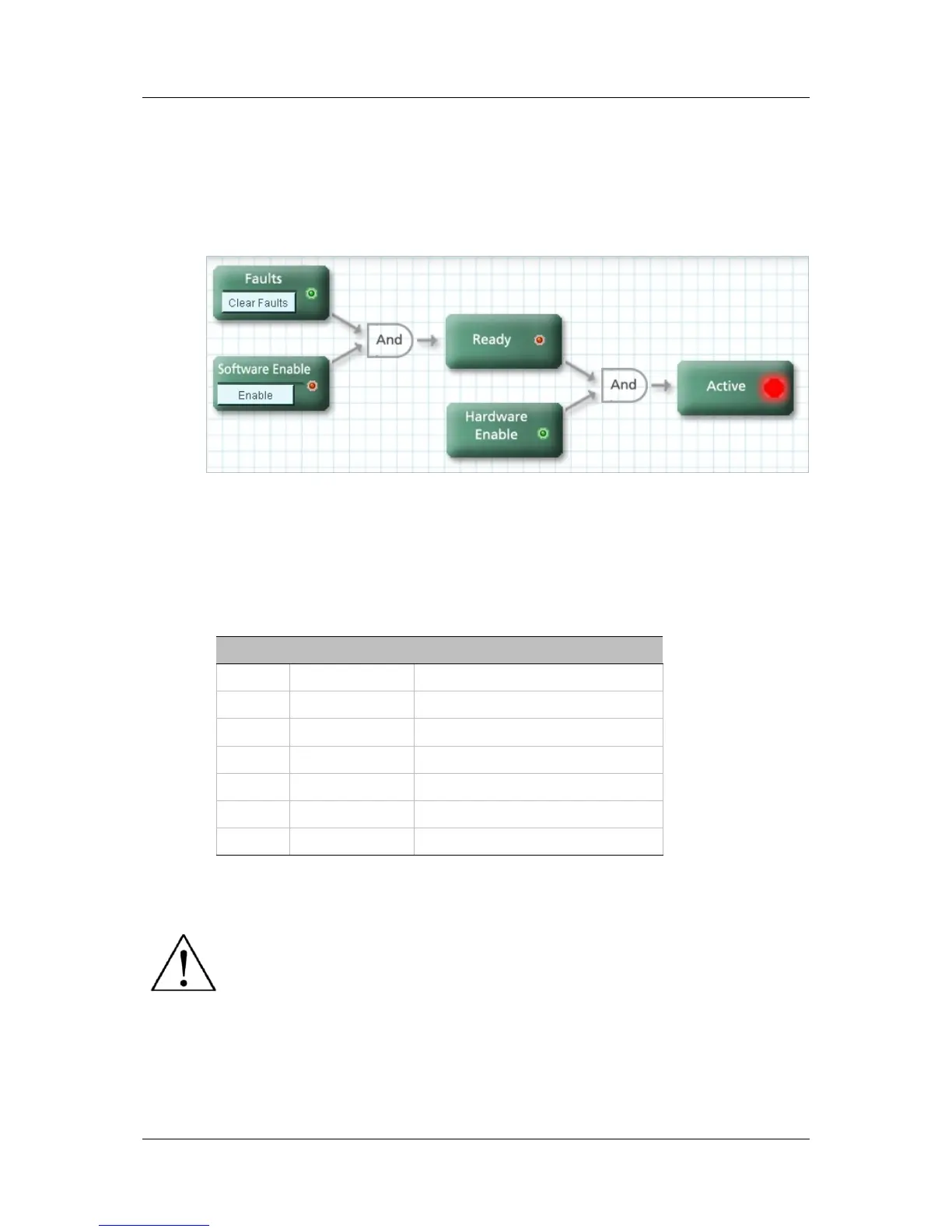
Figure 4-1. Drive Enable Conditions (ServoStudio diagram)
4.4.2 Operation Mode Codes
Once the drive is ready for operation, the 7-segment display shows a steadily-lit
single digit, indicating the operation mode currently in effect.
Table 4-1. Operation Mode on 7-Segment Display
Display Name Description
. Drive enabled
0 OPMODE 0 Serial velocity control
1 OPMODE 1 Analog velocity control
2 OPMODE 2 Serial current control
3 OPMODE 3 Analog current control
4 OPMODE 4 Master/slave gearing control
8 OPMODE 8 Position control
For more information, refer to the section Drive Status 7-Segment Display.
Caution: Enabling the drive might cause the motor to move.