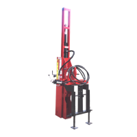
5. If traveling more than 100 feet to drive the
first post, remove road lock pin (B8). Raise
drive ram (A1) and install the road lock pin
in the lower “transport” position. The Post
Driver can now be moved to the work site.
(A1) Drive Ram. (B8) Road Lock Pin (transport position).
Preparing to Drive a Post
IMPORTANT NOTICE
If operating on uneven ground, make sure the
stabilizer legs firmly contact the ground at each
new fence post location. If necessary, loosen
the stabilizer leg lock bolts to readjust the
stabilizer legs, as needed. Failure to do so can
cause damage to the Post Driver components.
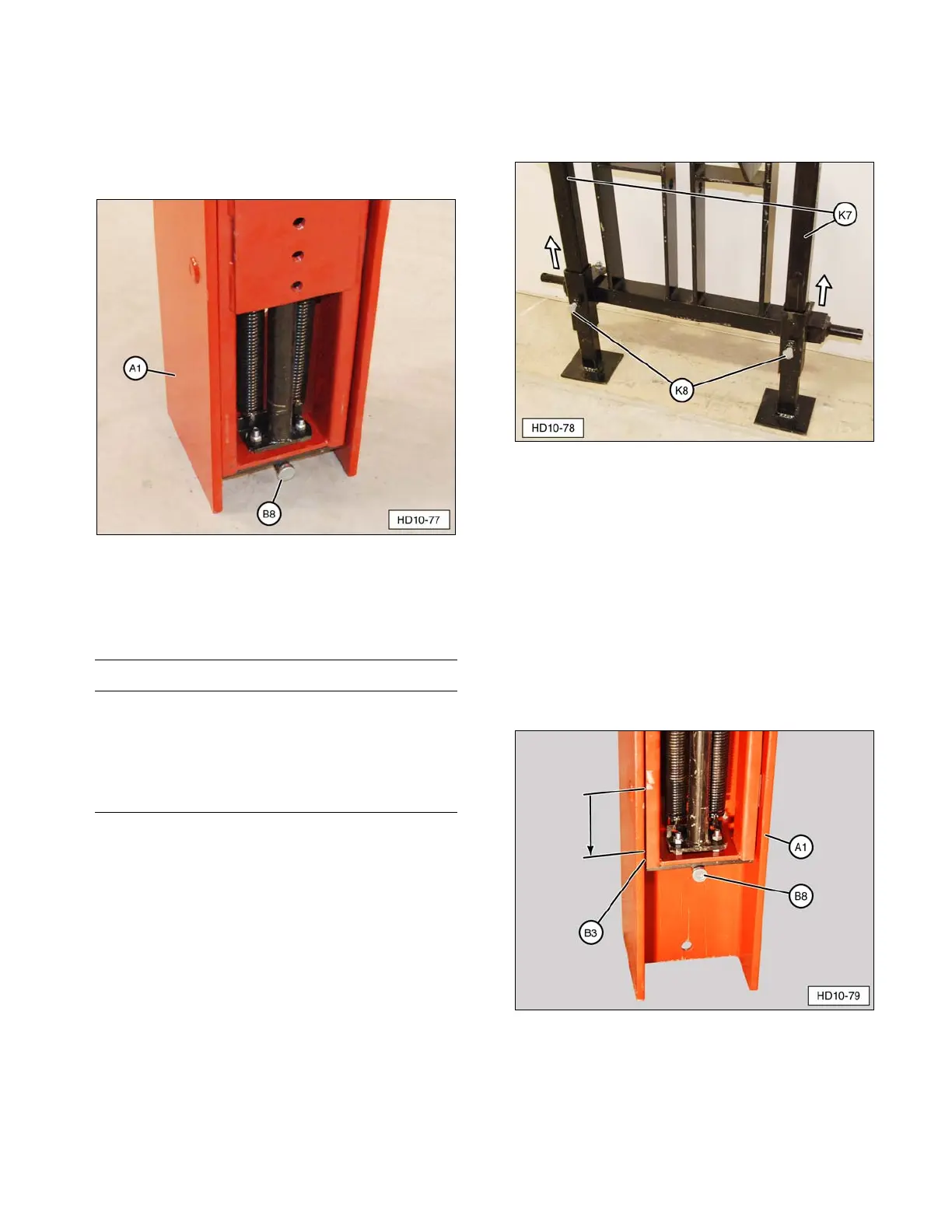
1. Loosen stabilizer leg lock bolts (K8) and
raise up each stabilizer leg (K7). Tighten
the lock bolts to support the stabilizer legs.
(K7) Stabilizer Leg. (K8) Lock Bolts.
2. Position the tractor or power source in
place to drive the first fence post.
3. Set the brakes on the tractor or power
supply. If the machine is equipped with an
automatic transmission, the transmission
must be in PARK.
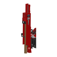
4. Remove road lock pin (B8) and lower drive
ram (A1) until it rests on main carriage
channel lower rubber bumpers (B3) (store
road lock pin in a secure location).
(A1) Drive Ram. (B3) Main Carriage Channel Lower
Rubber Bumper. (B8) Road Lock Pin.
23