11. Install piston guide (C10) and new
self-locking piston guide nut (C11), using
a 1-1/4” wrench to hold the piston guide
while installing the piston guide nut. Do
not over-tighten the self-locking nut.
Piston guide (C10) must be able to rotate
on cylinder piston rod (C3).
12. Install cylinder piston rod (C3) assembly
into drive cylinder tube (C2).
NOTE: Care must be taken during installation
to prevent scoring of cylinder piston rod (C3) or
the inside of drive ram cylinder tube (C2).
13. Apply paste-type thread sealant (T12) on
drive cylinder tube (C2) external threads
and install cylinder cap assembly (C7).
Tighten cap securely.
IMPORTANT NOTICE
Hydraulic system fittings that require a thread
sealant must be installed with a paste-type
sealer only. Do not use a tape-type sealer, such
as Teflon Tape, as this can contaminate the
system and voids the valve warranty.
14. To install drive cylinder assembly (C1) in
the Post Driver, follow the instructions in
the Main Carriage Channel Assembly
section.
Main Carriage Channel Assembly
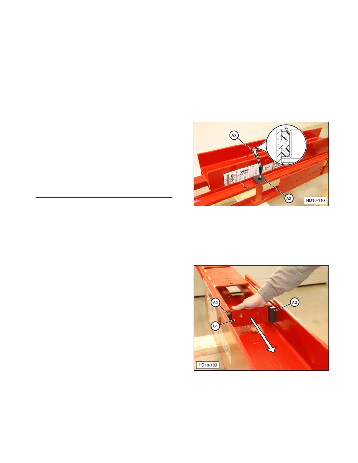
1. Install guide block shims (A3) and guide
blocks (A2) on the pins inside the drive ram
I-beam. Make sure the shims are installed
in their original locations.
NOTE: Chamfer (rounded edges) on guide
blocks must be positioned horizontally to
match the chamfer on the inside of the main
carriage channel frame.
(A2) Guide Blocks. (A3) Guide Block Shims.
2. Lubricate the guide blocks with clean oil to
reduce friction. Get assistance to slide
main carriage channel (B1) over guide
blocks (A2) from the top of the drive ram.
(A2) Guide Blocks. (B1) Main Carriage Channel.
35