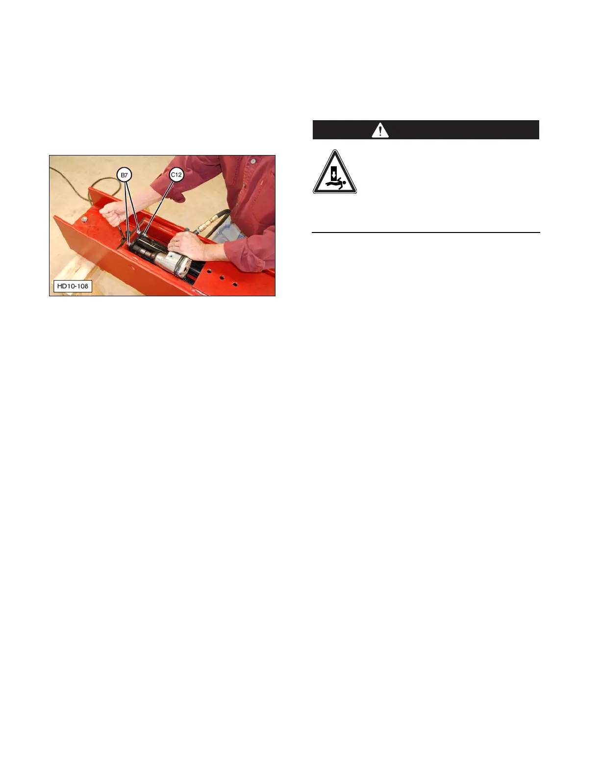
b. Completely tighten road lock bracket
nuts (B7) that were left loose in Step 7.
c. Completely tighten self-locking nuts
(C12) that were left loose in Step 8.
Tighten each nut slightly, in turn, to
align the drive cylinder inside the main
carriage channel.
(B7) Road Lock Bracket Nuts. (C12) Self-locking Nuts.
13. Pull main carriage channel (B1) down and
install road lock pin (B8) and Lynch pin
(B9) in lower hole in drive ram (A1).
14. To avoid binding, the drive cylinder and
rod must be parallel to the sides of the
main carriage channel. If necessary,
make the following adjustments:
a. Make sure the top drive ram cylinder
self-locking nut is loosened 1/2 turn.
b. Loosen lower drive ram cylinder
self-locking nuts (C12).
c. Tighten or loosen each nut slightly, in
turn, to align the drive cylinder inside
the main carriage channel.
NOTE: Self-locking nuts (C12) do not have to
be completely tightened against the lower
spring bracket.
Forward and Side Tilt Cylinder
Maintenance
Cylinder Disassembly
Removing tilt cylinder(s) from the
assembled Post Driver can cause an
unstable condition. To avoid
personal injury or death, make
sure the drive ram is stable and fully
supported by other means before removing
the tilt cylinders for service.
1. If removing cylinder(s) from the assembled
Post Driver, make sure the drive ram is fully
supported by other means, such as a
suitable overhead lifting device, before
disconnecting the tilt cylinders.
2. Disconnect the tilt cylinder hydraulic hoses
from the hydraulic control valve. Plug the
hoses and control valve fittings to prevent
dirt from entering the hydraulic system.
NOTE: Be prepared to collect any hydraulic
fluid that drains from the cylinder and hoses
into a suitable container.
3. Clean the outside of tilt cylinders (F3, F4).
Remove the tilt cylinders from the base
plate by removing the mounting pins.
4. Inspect the tilt cylinder mounting points.
Replace any worn or damaged
components.