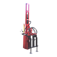
9. Attach drive cylinder piston rod (C3) to the
top of the drive ram I-beam using new lock
washer (C16) and new self-locking nut
(C4). Tighten the nut just enough to fully
engage the threads.
(C3) Drive Cylinder Piston Rod. (C4) Self-Locking Nut.
(C16) Lock Washer.
10. Attach springs (C14) to upper spring
bracket (A11). Hook retaining strap (T19)
to spring clips, as shown.
(A11) Upper Spring Bracket. (C14) Springs.
(T19) Retaining Strap.
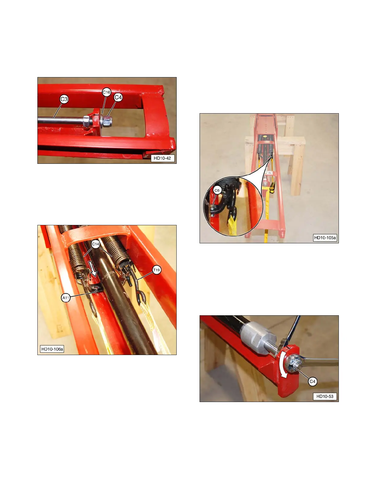
11. Install the upper spring bracket on the
drive ram assembly.
a. Route retaining strap around top of
drive ram lift yoke bar, as shown.
b. Use the retaining strap to pull (stretch)
the springs just enough to align holes
in upper spring bracket and drive ram
assembly.
c. Install upper spring bracket hardware
(C8) and tighten securely.
d. Carefully release tension on the
retaining strap and remove it from the
Post Driver.
(C8) Upper Spring Bracket Bolts, Washers, and Nuts.
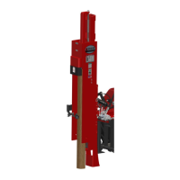
12. Align the drive ram cylinder.
a. Hold the lower nut with a 1-1/8” wrench
and tighten self-locking nut (C4) using
a 1-1/16” wrench. Then loosen the
self-locking nut 1/2 turn (180 degrees).
(C4) Self-locking Nut.
37