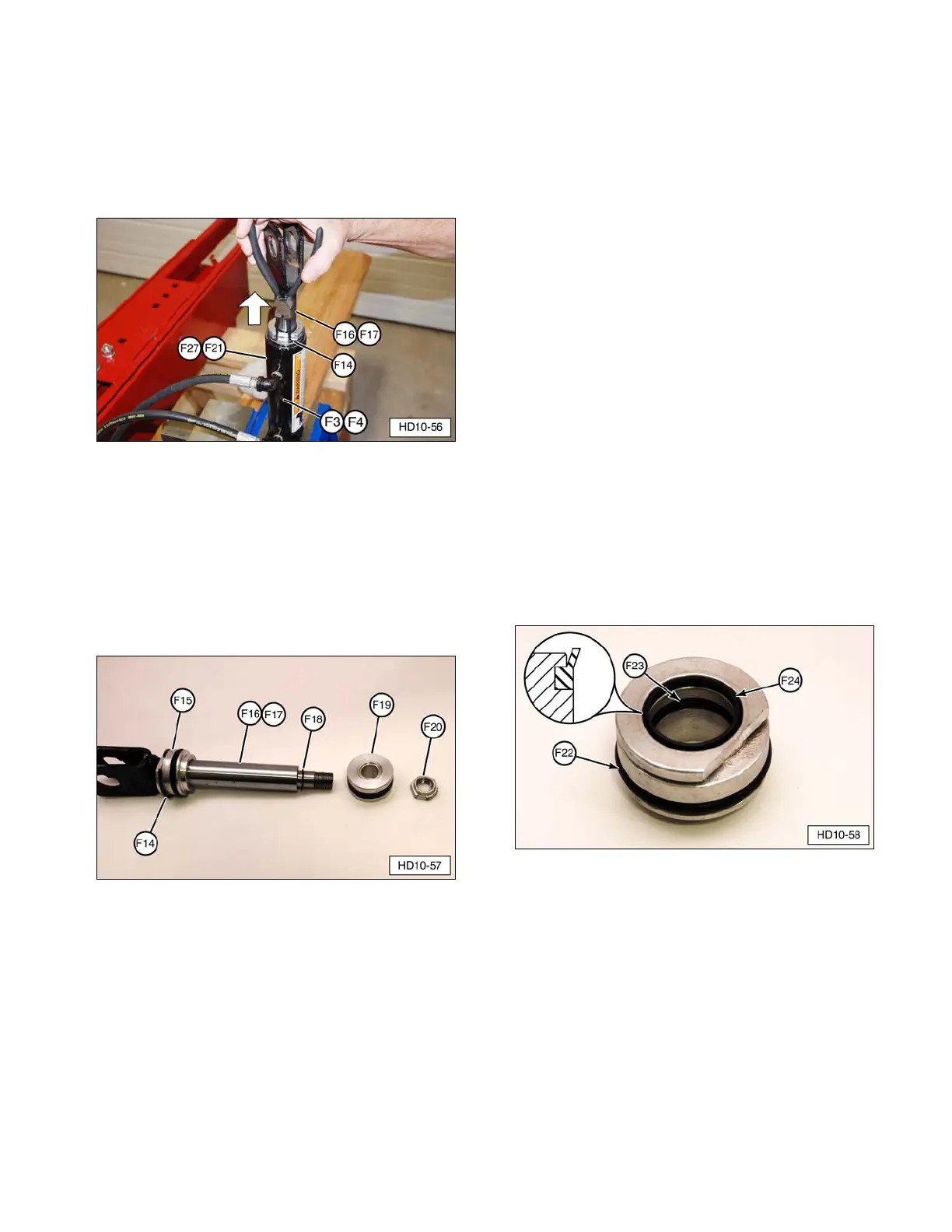
5. Carefully clamp tilt cylinder (F3 or F4)
mounting tube in a vise. Completely
compress internal cylinder cap snap ring
(F14) and pull cylinder rod assembly
(F16 or F17) out of tilt cylinder tube (F21 or
F27).
(F3, F4) Cylinder Assembly (forward or side tilt).
(F14) Cylinder Cap Snap Ring. (F16, F17) Cylinder Rod
Assembly (forward or side tilt). (F21, F27) Cylinder Tube
(forward or side tilt).
6. Disassemble cylinder rod (F16, F17) by
removing cylinder rod nut (F20), piston
(F19), piston to cylinder rod seal (F18), and
cylinder cap (F15) from the cylinder rod.
(F14) Snap Ring. (F15) Cylinder Cap.
(F16 or F17) Cylinder Rod. (F18) Cylinder Rod Seal.
(F19) Piston. (F20) Cylinder Rod Nut.
7. Inspect the cylinder rod sealing surface for
any dents, bends, nicks, pitting, scratches,
scoring, or rust. Replace any worn or
damaged components.
8. Use a sturdy seal pick to remove the seals
from the cylinder piston and discard.
Clean and inspect the piston and replace if
worn or damaged.
9. Clean the inside of the tilt cylinder tube and
inspect for scratches with raised (above the
surface level) edges, wear, rust, cracks,
and pitting. Replace any worn or damaged
tube.
10. Use a sturdy seal pick to remove the seals
from the cylinder cap and discard. Clean
and inspect the cap and replace if worn
or damaged.
Cylinder Assembly
1. Make sure all tilt cylinder components are
clean and free of rust.
2. Lubricate the new seals with clean
hydraulic fluid.
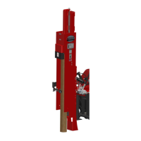
3. Install new internal O-ring seal (F23) and lip
seal (F24) (raised lip up) inside the cylinder
cap. Install new O-ring seal (F22) in the
O.D. groove. Install new snap ring (F14),
not shown, in the top “cut-a-way” groove.
(F22) External O-ring Seal. (F23) Internal O-ring Seal.
(F24) Internal Lip Seal.
39