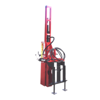
4. Install new scraper seal (F25) in the
cylinder piston groove, followed by O-ring
seal (F26), and the second scraper seal
(F25). Rounded (concave) surface of each
scraper seal (F25) must face (contact)
larger O-ring seal (F26).
(F25) Scraper Seal. (F26) O-ring Seal.
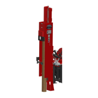
5. Install new O-ring seal (F18) on the
threaded end of cylinder rod (F16 or F17).
6. Lubricate the ID of cylinder cap (F15) with
clean hydraulic oil and install the cap onto
cylinder rod (F16 or F17) with the snap ring
groove facing up (toward the cylinder rod
mounting eye).
7. Lubricate the ID of cylinder piston (F19)
with clean hydraulic oil. Install the cylinder
piston on cylinder rod (F16 or F17) with the
O-ring relief (groove) (A) toward O-ring seal
(F18). Install new self locking nut (F20) and
tighten securely.
(F14) Snap Ring. (F15) Cylinder Cap.
(F16 or F17) Cylinder Rod. (F18) O-ring Seal.
(F19) Cylinder Piston (with seal). (F20) Self Locking Nut.
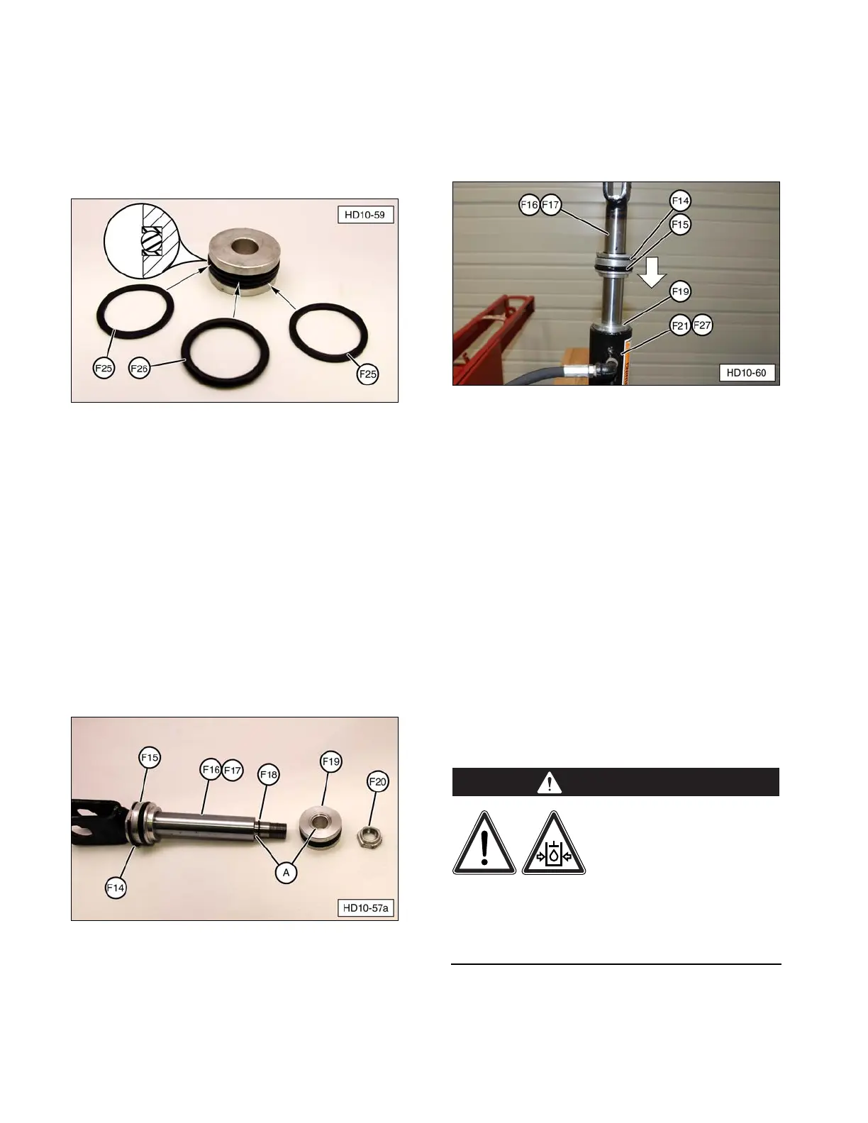
8. Lubricate cylinder tube (F21, F27) bore,
piston (F19) seals, and cylinder cap (F15)
seals. Install cylinder rod (F16, F17)
assembly into the cylinder tube, being
careful not to damage any seals.
(F14) Snap Ring. (F15) Cylinder Cap.
(F16 or F17) Cylinder Rod. (F19) Cylinder Piston
(with seal). (F21, F27) Cylinder Tube.
9. Push cylinder rod into cylinder tube until
snap ring (F14) in cylinder cap (F15)
contacts the top of the tube.
10. Use heavy-duty snap ring pliers to
completely compress snap ring (F14).
Push cylinder cap (F15) into cylinder tube
until the snap ring is completely seated in
the snap ring groove.
NOTE: It may be necessary to use a soft
(brass or wood) drift to tap the cylinder cap
and snap ring into place. Use caution not to
damage the aluminum cylinder cap.
Make sure the snap ring
is completely seated in
the cylinder tube groove.
Failure to seat the snap
ring in the groove can cause the cylinder cap
to be explosively ejected from the tilt
cylinder tube when hydraulic pressure is
applied, resulting in serious injury or even
death.