Service Procedures
To avoid personal injury or death,
carefully read and understand all
instructions before attempting to
assemble and/or operate the Post
Driver. Do not operate or work on equipment
unless you read and understand the
instructions and warnings in this and all
other applicable manuals. Contact Shaver
Manufacturing Company if any of the
instructions provided are unclear or not
understood. Proper care is your
responsibility. Always follow all State and
Federal health and safety laws and/or local
regulations.
To help prevent personal
injury, protective
equipment must be worn
during Post Driver
assembly, operation, and
maintenance. Personal
protective equipment
should include, but not
be limited to, safety glasses, hearing
protection, protective gloves, and steel toe
footwear.
Before making any
adjustments on the Post
Driver, ensure that all
hydraulic levers are in the
neutral position. Always shut off the
machine, set parking brake, and remove key
before performing any service.
Personal injury can result
from slips or falls. DO
NOT leave tools or parts
laying around the work
area, and clean up all spilled fluids
immediately.
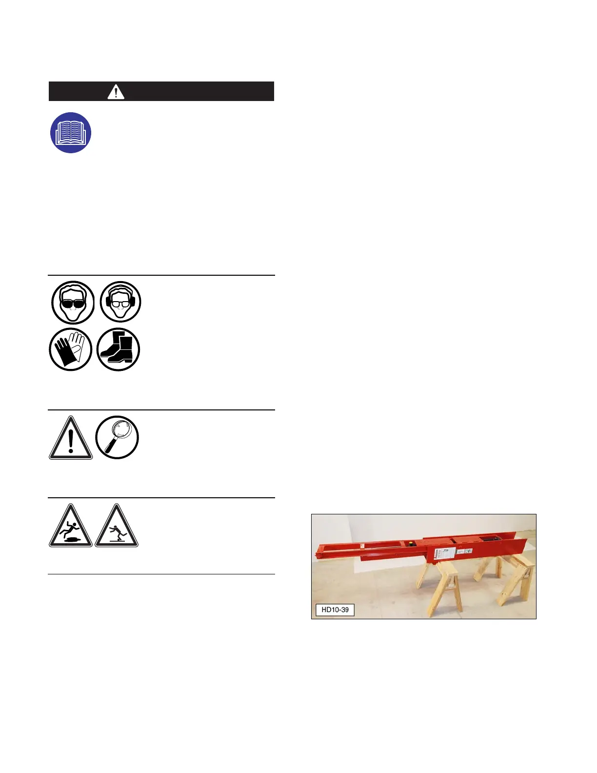
NOTE: Disassembly, assembly, and/or
associated repairs must be performed with the
main carriage channel and drive ram in a
horizontal position, such as on a suitable
pallet, or heavy-duty support stands.
Refer to Dismounting Post Driver from
Machine/Power Source section for steps to
remove Post Driver from a tractor or other
power source.
Three-Point Hitch/Post Driver
Disassembly
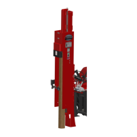
1. Secure the Post Driver upright [main
carriage channel (B1) and drive ram (A1)
assembly] to an appropriate overhead
lifting device to prevent tipping.
2. Disconnect drive cylinder to valve hose
(G15) and drain fluid into a suitable
container.
3. On hydraulic base plate Post Drivers,
tighten cylinder stop bolt (F11). Disconnect
four tilt cylinder hoses (H5) from hydraulic
control valve (H1), and drain fluid into a
suitable container.
4. Remove Lynch pins (D7) and two channel
mounting pins (D6) that connect the base
plate to the Post Driver upright (applies to
manual or hydraulic models).
NOTE: If necessary, lubricate channel
mounting pins with penetrating oil to assist pin
removal.
5. With assistance, carefully move the three-
point hitch weldment/base plate assembly
away from the Post Driver upright. Store
weldment/base plate assembly in a safe
location.
6. The upright assembly is heavy. Use an
appropriate lifting device to position the
Post Driver assembly horizontally, on
suitable stands, pallet, or blocks on the
ground.