IMPORTANT NOTICE
If the tilt cylinder hoses are attached differently
than shown, the control of the drive ram will not
be as described in this manual.
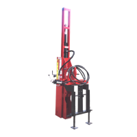
d. Hydraulic base plate only. Attach
forward tilt cylinder hoses (H5) between
forward tilt cylinder (F3) and triple lever
control valve (H1), as shown.
(F3) Forward Tilt Cylinder. (H1) Triple Lever Control
Valve. (H5) Tilt Cylinder Hoses.
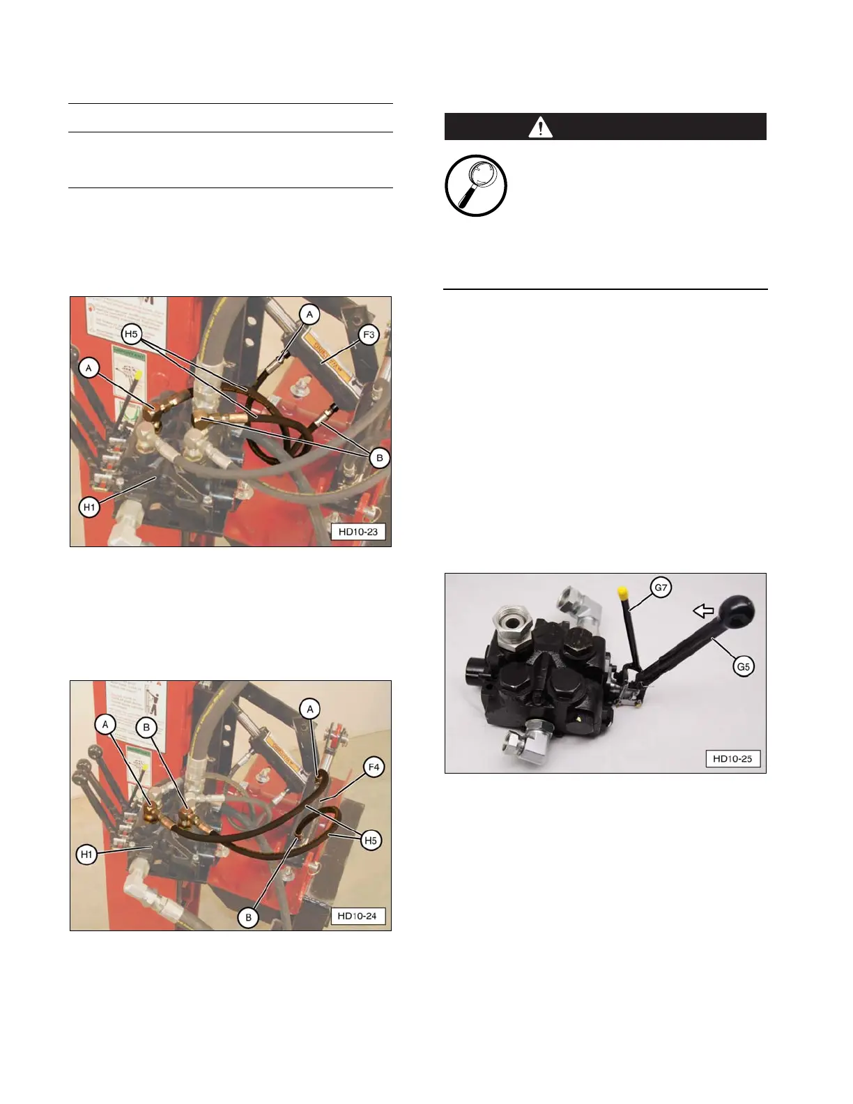
e. Hydraulic base plate only. Attach side
tilt cylinder hoses (H5) between side tilt
cylinder (F4) and triple lever control
valve (H1), as shown.
(F4) Side Tilt Cylinder. (H1) Triple Lever Control Valve.
(H5) Tilt Cylinder Hose.
Safety Stop Adjustment
To avoid serious injury, inspect the
control valve safety stop before
using the Post Driver the first time
and/or before each daily use.
Adjust the safety stop as needed, per the
following procedure. Make sure all control
valve hardware is tight. Always replace worn
or damaged parts before use.
The control valve safety stop prevents
unintentional activation of the Post Driver
control valve and must be functional at all
times.
If the Post Driver is operational, make sure the
machine/power source is OFF, parking brake
is set, road lock pin is installed, and all
hydraulic pressure is released (zero pressure).
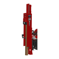
1. Attempt to push main hydraulic control
valve lever (G5) forward (away from
operator) without squeezing (pulling) yellow
tipped control valve safety lever (G7).
(G5) Main Hydraulic Control Valve Lever. (G7) Control
Valve Safety Lever.
2. If main hydraulic control valve lever (G5)
CAN move forward more than 1/4”, the
safety stop must be adjusted.