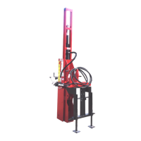
3. Attach the hydraulic hoses.
(G15) Valve to Drive Ram Hose. (G17) Pressure Supply
Hose. (G20) Return Hose.
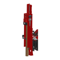
a. Apply paste-type thread sealant (T12)
to hose fitting threads and install hose
(1” I.D. x 35”) (G15) between hydraulic
control valve (G1 or H1) and drive
cylinder assembly (C1). Tighten the
hose fittings securely.
(C1) Drive Cylinder Assembly. (G1) Control Valve
(Single Lever), not shown. (G15) Valve to Drive Ram
Hose. (H1) Control Valve (triple lever).
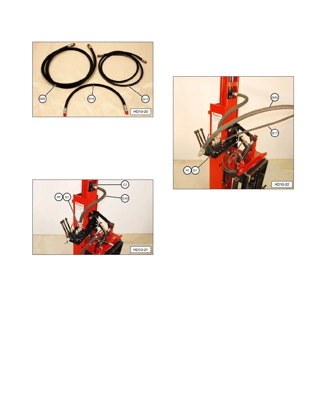
b. Connect threaded fitting on pressure
hose (1/2” x 120”) (G17) to control
valve (G1 or H1) swivel fitting.
c. Connect threaded fitting on return hose
(1” x 120”) (G20) to control valve
(G1 or H1) swivel fitting.
(G1) Single Lever Control Valve, not shown.
(G17) Pressure Hose. (G20) Return Hose.
(H1) Triple Lever Control Valve.
NOTE: The hydraulic control valve for manual
base plate (E2) has a single control lever.
Installation of supply, return, and drive ram
hoses are the same.
15
 Loading...