Main Carriage Channel
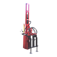
1. With road lock pin (B8) installed in lower
hole of drive ram (A1), use a suitable
overhead lifting device to raise (stand up)
main carriage channel (B1).
(A1) Drive Ram. (B1) Main Carriage Channel.
(B8) Road Lock Pin.
The main carriage channel
assembly is tall and heavy. To
avoid tip over, resulting in serious
injury or death, leave the overhead
lifting device attached to the main carriage
channel while assembling components.
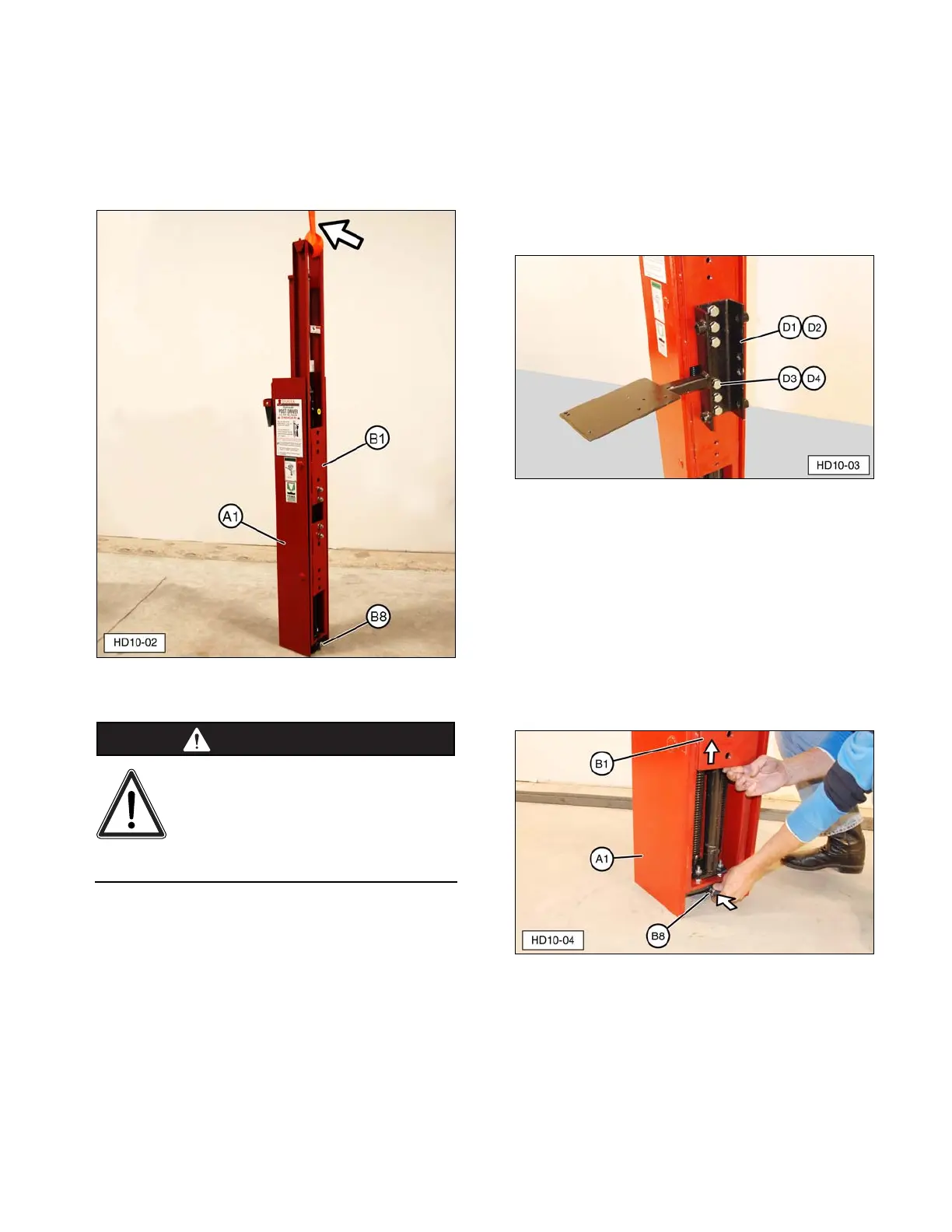
2. Install appropriate short channel bracket
(D1, D2) using bolts (D3) and lock washers
(D4) (6 each). Tighten completely.
NOTE: Hydraulic short channel bracket (D2)
shown. Manual short channel bracket (D1)
installation is the same.
(D1) Manual Short Channel Bracket (not shown).
(D2) Hydraulic Short Channel Bracket (shown).
(D3) Bolt. (D4) Lock Washer.
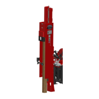
3. Remove road lock pin (B8) from lower hole
in drive ram (A1). Use spring tension to
help raise main carriage channel (B1) and
insert road lock pin (B8) in upper hole (tool
storage position) in drive ram (A1). Install
Lynch pin (B9), not shown, to secure road
lock pin.
(A1) Drive Ram. (B1) Main Carriage Channel.
(B8) Road Lock Pin.