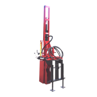
b. Assemble control valve linkage. Install
lever(s) (G5), control valve safety lever
(G7), return spring (G10), and lever
linkage (G11, G12, G23), as shown.
Secure with cotter pins (G13). Refer to
photographs for correct placement and
orientation.
(G1) Manual Tilt Base Control Valve.
(H1) Hydraulic Tilt Base Control Valve.
(G5) Control Valve Lever(s). (G7) Control Valve Safety
Lever. (G10) Safety Lever Return Spring. (G11) Clevis
Pin. (G12) U-Link. (G13) Cotter Pin(s). (G23) Flat Link.
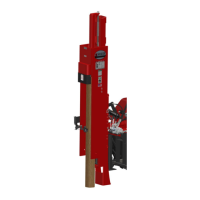
(H1) Hydraulic Valve Control Lever Linkage.
(G5) Control Valve Lever(s). (G10) Safety Lever Return
Spring. (G11) Clevis Pin. (G12) U-Link.
(G13) Cotter Pin(s). (G23) Flat Link.
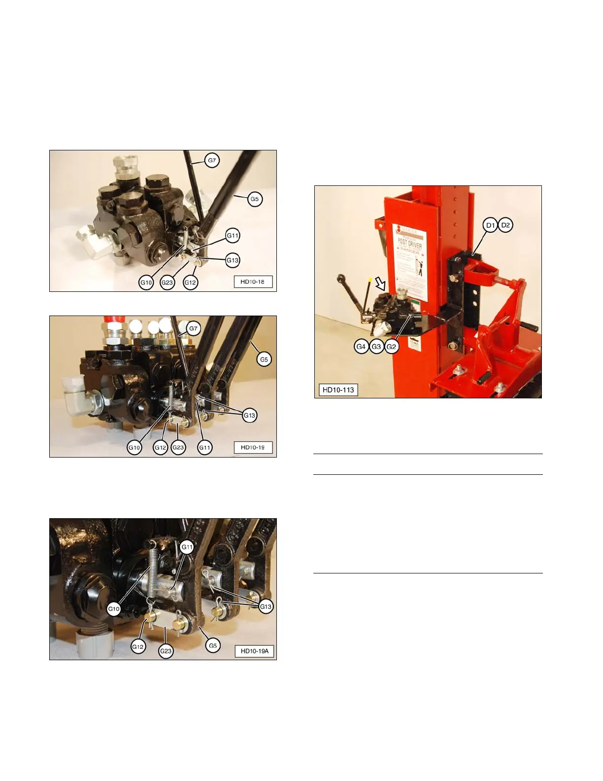
2. Install the hydraulic valve on short channel
bracket (D1, D2) using three 5/16-18 x 3”
valve mounting bolts (G2), washers (G3),
and nuts (G4). Do not over-tighten the
hardware, which can warp valve body.
NOTE: Single lever hydraulic valve shown.
Installation of three lever hydraulic valve is the
same.
(D1) Hydraulic Short Channel Bracket. (D2) Manual
Short Channel Bracket, shown. (G2) Bolt. (G3) Washer.
(G4) Nut.
IMPORTANT NOTICE
The hydraulic valve and cylinder(s) can be
damaged by contamination (dirt and debris)
from the oil in the tractor or power source.
Ensure the oil is clean and properly filtered
before connecting the Post Driver to a hydraulic
power source. Failure to follow oil cleanliness
standards voids the Shaver Post Driver
warranty.
14