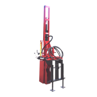
3. The main carriage channel should slide
back and forth freely.
4. With the drive ram assembly horizontal,
check the up and down movement of the
main carriage channel in the drive ram
I-beam. Up and down movement should
not be less than 1/4” or more than 1/2”.
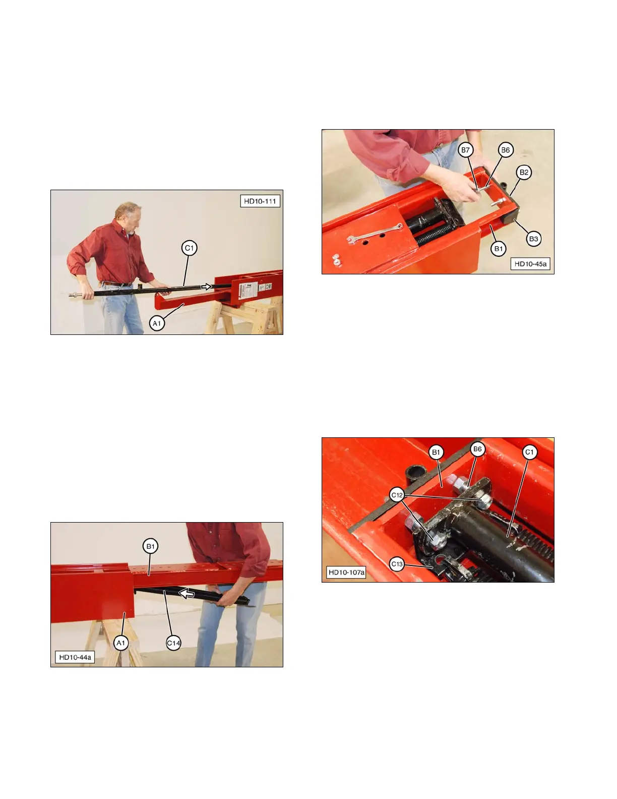
5. Install drive cylinder (C1) in drive ram
assembly (A1) from the top (upper end).
(A1) Drive Ram. (C1) Drive Cylinder.
NOTE: Hydraulic drive ram cylinder (C1) must
be inserted in main carriage channel (B1)
before springs (C14) are inserted. Position the
cylinder laying loose inside the main carriage
channel.
6. Install springs (C14) from the bottom of the
Post Driver between drive ram (A1) I-beam
and main carriage channel (B1), and slide
into position.
(A1) Drive Ram. (B1) Main Carriage Channel.
(C14) Springs.
7. If removed, install two rubber bumpers (B3)
on road lock bracket (B2). Install the road
lock bracket on main carriage channel (B1)
with bolts (B6) and road lock bracket nuts
(B7). Leave nuts slightly loose.
(B1) Main Carriage Channel. (B2) Road Lock Bracket.
(B3) Rubber Bumper. (B6) Bolts. (B7) Road Lock
Bracket Nuts.
8. Slide main carriage channel (B1) up
(forward) and install lower spring bracket
(C13) and drive cylinder assembly (C1)
onto road lock bracket bolts (B6). Thread
two new self-locking nuts (C12) onto bolts.
Install nuts just enough to fully engage
threads, as shown.
(B1) Main Carriage Channel. (B6) Road Lock Bracket
Bolts. (C1) Drive Cylinder Assembly. (C12) Self-locking
Nuts. (C13) Lower Spring Bracket.
36