4-13
4.2 Software Basic Operation
AA-6800/6650 Instruction
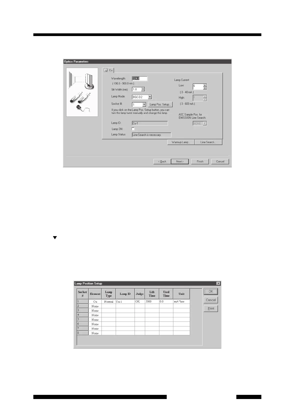
4.2.1.8 Optics Parameters
Figure 4.13 [Optics Parameters] Page
The wavelength, slit width, socket number, lamp current and lamp mode for the element to be firstly analyzed
are set here. Note that these settings are only for the element to be firstly analyzed (the element that was
specified in [Measurement Element] at the right lower on the [Element Selection] page or [Connect to
Instrument/Send Parameters] page).
(1) For the [Wavelength] and [Slit Width], you usually need not to change the value since the appropriate set
values in the cookbook for each element are indicated. If you want to change them specially, enter the
numeric value for wavelength and select a slit width from 6 levels on the list that is displayed by clicking on
the [ ] button.
(2) Click on the [Lamp Pos. Setup] button. Then [Lamp Position Setup] dialog box will appear. Enter the
[Element] and [Lamp Type] of the lamp actually mounted for each socket number. Select the element from
the drop-down list. Select [Normal] or [SR] for [Lamp Type] from the drop-down list. Then select lamp ID in
[Lamp ID] field. You can turn lamp turret manually and change lamp while the [Lamp Position Setup] dialog
box is displayed. Click on [OK] to return to the [Optics Parameters] page.
Figure 4.14 [Lamp Position Setup] Dialog Box
 Loading...