4.5
Plumbing
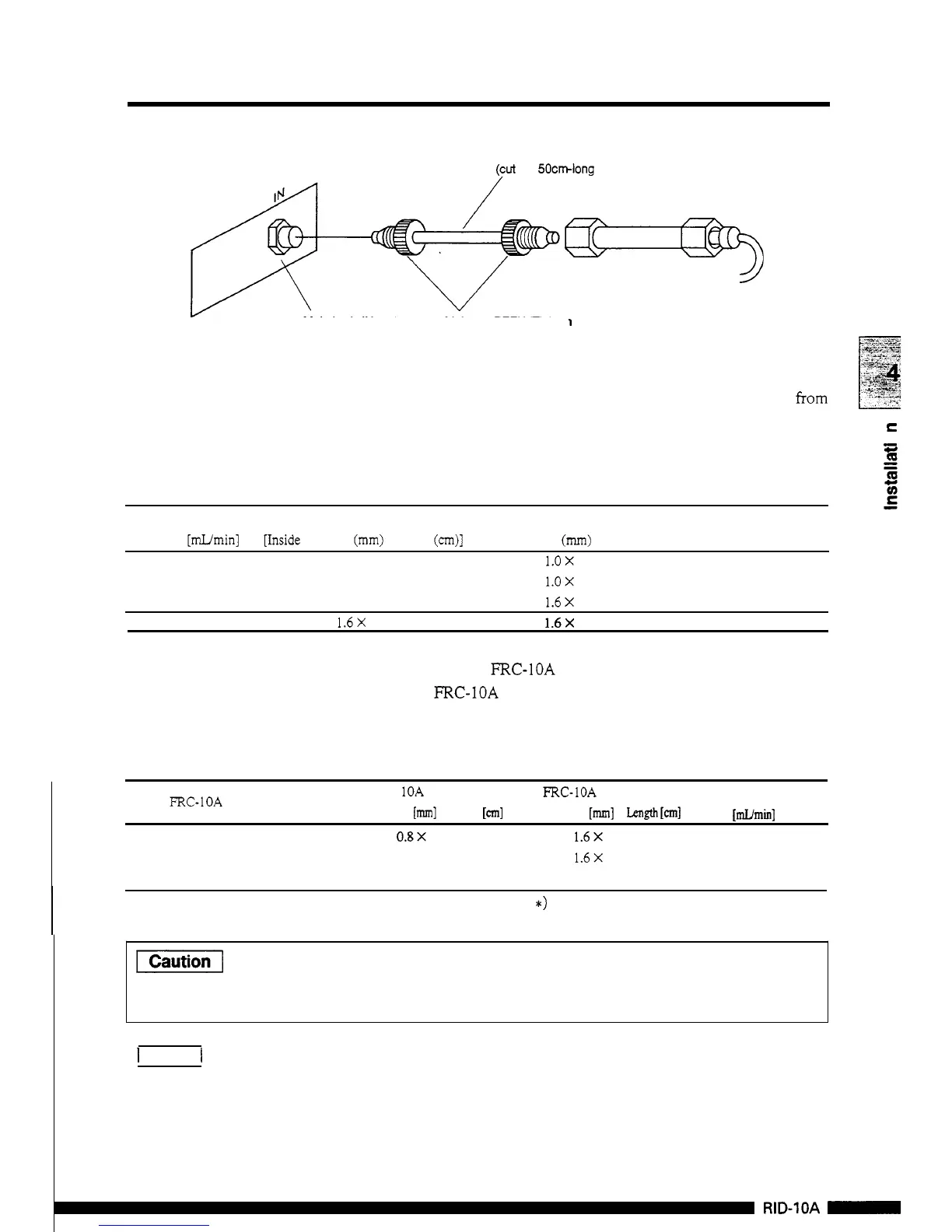
Connections
Tubing
(cut
the 50cmlong tube for use)
Manual injector
Main
body
IN
port
Male
nut
PEEK
(Tighten by
hand)
Manual injector
I
by
hand)
5.
Detector outlet side piping
(1)
Prepare a waste liquid bottle.
Connect the
drain
tube to the detector outlet. Select one
from
applied flow rate. Insert the outlet
of
the
drain
tube into the
waste liquid bottle.
the
drain
tubes listed
in
the table below depending on the
C
0
m
-
c
Max.
flow rate
Drain
tube
For extension
Remarks
[Wmin]
Fside diameter (mm)
x
length
(cm)]
[Inside diameter
(mm)
x
length (cm)]
3
0.3
X
100
1.ox
100
5
0.5
X
100 1.ox 100
20
0.8 X
100 1.6X
100
150
1.6X 100
1.6X
100 At mode
L
(option)
When using the FFX-1OA fraction collector, connect the inlet tube
of
the FRC-1OA to the detector outlet directly. Note that the
maximum
flow rate varies depending on the preparative head
of
the
FRC.
FRC
-
1OA
inlet pipe
Inside diameter
[m]
x
Length
[cm]
FRC-10A outlet pipe
Inside
diameter
[mm]
x
Length
[cm]
Max.
operating
flow
rate
[mVmin]
Fraction correction head with valve
0.8X
100
1.6X 100
20
(150')
Fraction
correction head with valve
0.3
X
100 1.6X
100
3
Fraction correction head without valve
FRC- 1OA preparative
head
0.3
X
100
*)
An
optional flow selection
block
is necessary.
The solenoid valve and flow cells may
be
damaged by application
of
back
pressure which exceeds the detector resistance pressure.
Do
not use the pipes listed
in
the table which
are
out
of
range.
I
Note
1
To
prevent the detector
from
being damaged by back pressure, it is
useful to connect the relief valve (option) to the detector outlet
when the
unit
is
used with large flow rate, or the piping
is
clogged.
4
-
9
RID-1OA
-