23
9. Troubleshooting
If any malfunctions occur, refer to the following items after checking the power supply to the controller.
9.1 Indication
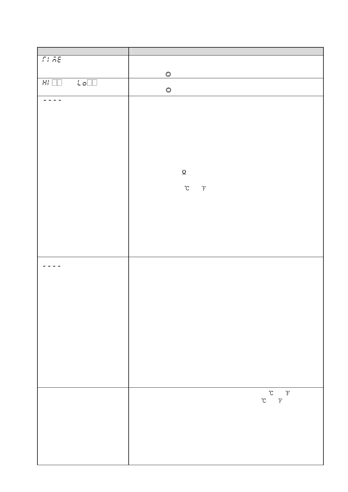
Problem Presumed cause and solution
“ ” is indicated in the PV
Display.
• The controller is in the EXCEEDED indicator lighting duration time
mode.
Press the key twice to revert to the PV/SV Display Mode.
“ ” or“ ” is
indicated in the PV Display.
• Maximum (Minimum) value is indicated.
Press the key once to revert to the PV/SV Display Mode.
“ ” is flashing in the PV
Display.
• Burnout of thermocouple, RTD or disconnection of DC voltage (0 to
1V DC)
Replace each sensor.
How to check whether the sensor is burnt out
[Thermocouple]
If the input terminals of the instrument are shorted, and if a value
around room temperature is indicated, the instrument is likely to
be operating normally, however, the sensor may be burnt out.
[RTD]
If approx. 100 of resistance is connected to the input terminals
between A-B of the instrument and between B-B is shorted, and
if approximate 0 (32 ) is indicated, the instrument is likely to
be operating normally, however, the sensor may be burnt out.
[DC voltage (0 to 1 V DC)]
If the input terminals of the instrument are shorted, and if a scaling
low limit value is indicated, the instrument is likely to be operating
normally, however, the signal wire may be disconnected.
• Check whether the input terminals of thermocouple, RTD or DC voltage
(0 to 1 V DC) are securely mounted to the instrument input terminal.
Connect the sensor terminals to the instrument input terminals securely.
“ ” is flashing in the PV
Display.
• Check whether input signal source for DC voltage (1 to 5 V DC) or
Direct current (4 to 20 mA DC) is disconnected.
How to check whether the input signal wire is disconnected
[DC voltage (1 to 5 V DC)]
If the input to the input terminals of the instrument is 1 V DC and
if a scaling low limit value is indicated, the instrument is likely to be
operating normally, however, the signal wire may be disconnected.
[Direct current (4 to 20 mA DC)]
If the input to the input terminals of the instrument is 4 mA DC and
if a scaling low limit value is indicated, the instrument is likely to be
operating normally, however, the signal wire may be disconnected.
• Check whether input signal wire for DC voltage (1 to 5 V DC) or Direct
current (4 to 20 mA DC) is securely connected to the instrument input
terminals.
• Check if polarity of thermocouple or compensating lead wire is correct.
• Check whether codes (A, B, B) of RTD agree with the instrument terminals.
The indication of PV Display is
abnormal or unstable.
• Check whether sensor input or temperature unit ( or ) is correct.
Select the sensor input and temperature unit ( or ) properly.
• Sensor correcting value is not suitable. Set it to a suitable value.
• Check whether the specification of the sensor is correct.
• AC leaks into the sensor circuit. Use an ungrounded type sensor.
• There may be equipment that interferes with or makes noise near
the controller.
Keep equipment that interferes with or makes noise away from the
controller.

 Loading...


