3
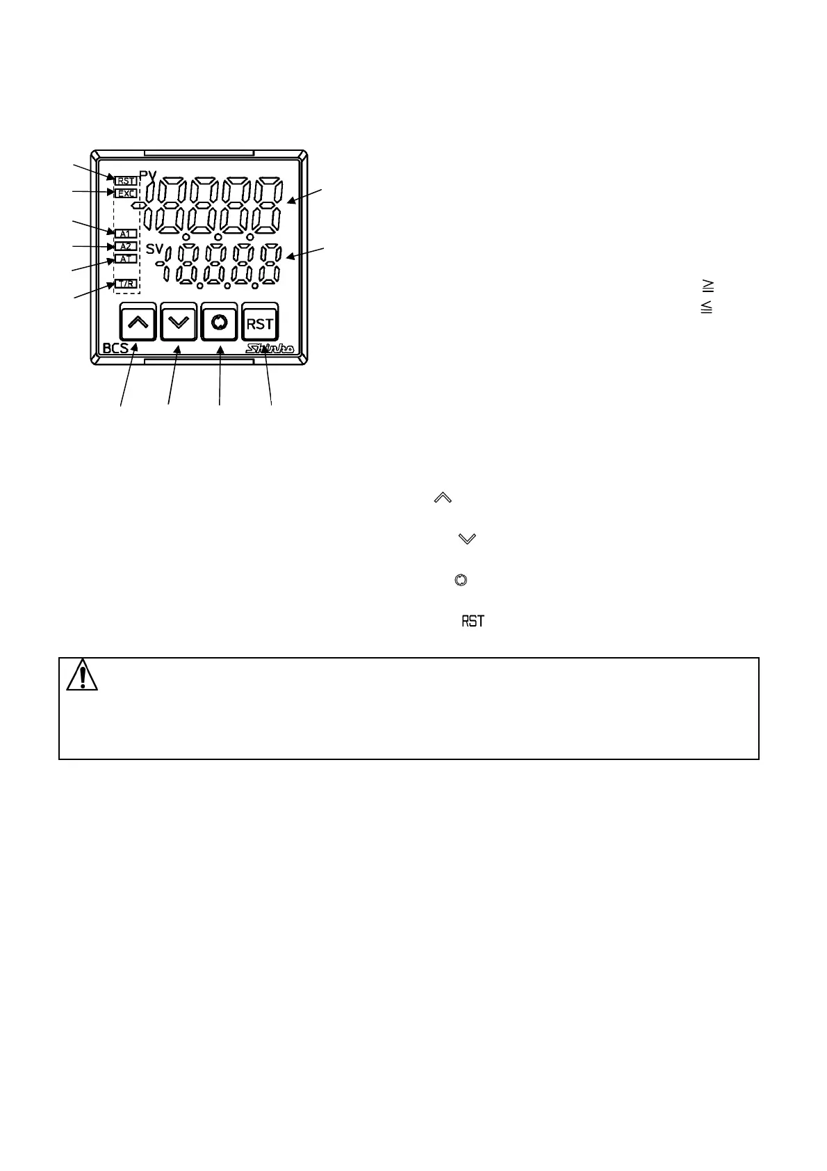
2. Name and functions of the sections
(1) PV Display:
Indicates the PV (process variable) with a red LED.
Indicates setting item characters during setting mode.
(2) SV Display:
Indicates the SV (desired value) with a green LED.
Indicates set (or selected) value during setting mode.
(3) RST (RESET) indicator: Lights when OUT1 (Limit control
output terminals 7 and 8) is OFF with a green LED.
(4) EXC (EXCEEDED) indicator:
High limit action: The yellow LED lights when PV SV.
Low limit action: The yellow LED lights when PV SV.
(5) A1 indicator: When A1 output is ON, the red LED lights.
(6) A2 indicator:
When A2 output (EV2 option) is ON, a red LED lights.
(7) AT (AUTO) indicator: The yellow LED flashes for auto-start
of the Limit control action.
(8) T/R indicator:
(Fig. 2-1) The yellow LED lights during Serial communication TX
output (transmitting) (C5 option).
(9) UP key ( ): Increases the numerical value, and
switches the setting item during setting mode.
(10) DOWN key ( ): Decreases the numerical value, and
switches the setting item during setting mode.
(11) MODE key ( ): Switches Indication selection mode or
setting mode, and registers the set (selected) value.
(12) RESET key ( ): High limit or low limit control action initiates.
Notice
When setting the specifications and functions of this controller, connect terminals 1 and 2 for power
source first, then set them referring to Section “5. Settings” before performing “3. Mounting to the
control panel” and “4. Wiring”.
(9)
(10)
(11)
(12)
(1)
(2)
(3)
(4)
(5)
(6)
(7)
(8)

 Loading...


