EasyManua.ls Logo

Shinko BCS2R Series User Manual

Shinko BCS2R Series
24 pages
To Next Page IconTo Next Page
Page #1 background imageLoading...
Page #1 background image
1
OGRANICZNIKI I BEZPIECZNIKI TEMPERATURY BCS2R, T7671
BCS2R,T7671
BCS23T7671E1 2016.02
To prevent accidents arising from the misuse of this controller, please ensure the operator receives this manual.
Safety precautions (Be sure to read these precautions before using our products.)
The safety precautions are classified into categories: Warning and “Caution”. Depending on circumstances,
procedures indicated by Caution may result in serious consequences, so be sure to follow the directions
for usage.
Warning
Warning
To prevent an electric shock or fire, only Shinko or other qualified service personnel may handle the inner
assembly.
To prevent an electric shock, fire or damage to the instrument, parts replacement may only be undertaken
by Shinko or other qualified service personnel.
Safety precautions
To ensure safe and correct use, thoroughly read and understand this manual before using this instrument.
This instrument is intended to be used for industrial machinery, machine tools and measuring equipment. Verify
correct usage after purpose-of-use consultation with our agency or main office. (Never use this instrument for
medical purposes with which human lives are involved.)
External protection devices such as protection equipment against excessive temperature rise, etc. must be
installed, as malfunction of this product could result in serious damage to the system or injury to personnel.
Also proper periodic maintenance is required.
This instrument must be used under the conditions and environment described in this manual. Shinko Technos
Co., Ltd. does not accept liability for any injury, loss of life or damage occurring due to the instrument being used
under conditions not otherwise stated in this manual.
Caution with respect to Export Trade Control Ordinance
To avoid this instrument from being used as a component in, or as being utilized in the manufacture of weapons of
mass destruction (i.e. military applications, military equipment, etc.), please investigate the end users and the final
use of this instrument. In the case of resale, ensure that this instrument is not illegally exported.
Caution
This instrument should be used according to the specifications described in the manual.
If it is not used according to the specifications, it may malfunction or cause fire.
Be sure to follow the warnings, cautions and notices. If they are not observed, serious injury or malfunction
may occur.
Specifications of the BCS2 and the contents of this instruction manual are subject to change without notice.
This instrument is designed to be installed in a control panel. If it is not, measures must be taken to ensure
that the operator cannot touch power terminals or other high voltage sections.
Be sure to turn the power supply to the instrument OFF before cleaning this instrument.
Use a soft, dry cloth when cleaning the instrument.
(Alcohol based substances may tarnish or deface the unit.)
As the display section is vulnerable, do not strike or scratch it with a hard object.
Any unauthorized transfer or copying of this document, in part or in whole, is prohibited.
Shinko Technos Co., Ltd. is not liable for any damages or secondary damages incurred as a result of using
this product, including any indirect damages.
Caution
Procedures which may lead to dangerous conditions and cause death or serious
injury, if not carried out properly.
Procedures which may lead to dangerous conditions and cause superficial to medium
injury or physical damage or may degrade or damage the product, if not carried out
properly.
Question and Answer IconNeed help?

Do you have a question about the Shinko BCS2R Series and is the answer not in the manual?

Shinko BCS2R Series Specifications

General IconGeneral
BrandShinko
ModelBCS2R Series
CategoryController
LanguageEnglish

Summary

Safety Precautions

Warning and Caution Definitions

Defines safety warnings and cautions for proper usage.

Operational Safety Guidelines

Key rules for safe operation, handling, environment, and specific cautions.

Export Trade Control Warning

Warning about illegal export and use in weapons.

Model Identification

Model Designation and Options

Details the model designation and its configurable options.

Reading the Model Label

Explains how to interpret the model label attached to the unit.

Control Panel Overview

PV and SV Displays

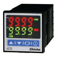
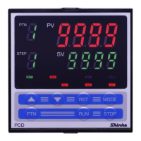
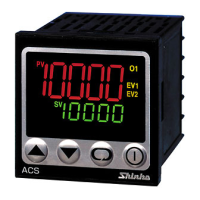
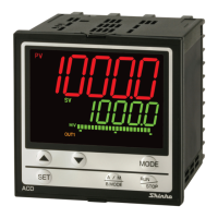
Indicates the process variable (PV) and desired value (SV).

Indicator Lights Functionality

Explains the function of RST, EXC, A1, A2, AT, and T/R indicators.

Keypad Operation

Describes the function of UP, DOWN, MODE, and RESET keys.

Important Operating Notice

Notice regarding connection and setting order before operation.

Mounting and Installation

Site Selection Criteria

Specifies environmental conditions and site requirements for installation.

External Dimensions and Panel Cutout

Provides dimensional drawings and required panel cutout for installation.

Mounting Procedures

Panel Mounting Precautions

Cautions for mounting to the panel, including torque and gasket use.

Wiring and Connections

Electrical Shock Hazard Warning

Critical warning about turning off power before wiring.

Terminal Identification and Wiring Notices

Explains terminals, wiring practices, external components, and interference.

Solderless Terminal Requirements

Specifies solderless terminal type and tightening torque for wiring.

Settings and Configuration

Operation Flowchart

Outlines the step-by-step procedure for setting input type, alarms, and SV.

Display Mode Navigation

Describes the main display modes and how to navigate them.

Main and Sub Setting Modes

Details how to enter and use main and sub setting modes for parameters.

Setup Mode Configuration

Input Type and Scaling Setup

Selects input type, unit, and sets scaling high/low limits.

PV Filter and Decimal Point

Sets PV filter constant and decimal point display for DC inputs.

Alarm and Action Settings

Configures alarm types, action modes (Energized/De-energized), hysteresis, and delay times.

Control and Start Mode Settings

Selects control modes, hysteresis, and auto/manual start.

Display Mode Functions

Switching Displayed Items

How to switch displayed items in PV/SV Display Mode.

Max/Min Value Display

How the PV/SV displays show maximum or minimum values.

Main Setting Mode Parameters

Setting Desired Value (SV)

Setting the desired value (SV) for the controller.

Setting Alarm Action Points (A1/A2)

Setting the action point for A1 and A2 outputs.

Sub Setting Mode Options

Value Lock and Sensor Correction

Locks set values and adjusts input based on sensor correction.

Communication Settings

Configures communication protocol, speed, parity, stop bits, and instrument number.

Setup Mode Details

Input Type and Scaling Configuration

Selects input type, unit, and sets scaling high/low limits.

PV Filter and Decimal Point Settings

Sets PV filter constant and decimal point display for DC input.

Alarm and Control Settings

A1 and A2 Alarm Type Configuration

Configures A1 and A2 alarm types and action modes.

A1 and A2 Hysteresis and Delay

Sets hysteresis and delay time for A1 and A2 alarms.

Limit Control and OUT1 Hysteresis

Selects limit control action and sets OUT1 hysteresis.

Operational Modes and Functions

Auto/Manual Start and EXCEEDED Indicator Unit

Sets start mode and unit for EXCEEDED indicator duration.

Sensor Correction and Output Logic

Sensor Correction Functionality

Adjusts input value based on sensor correction for accuracy.

Energized/De-energized Output Logic

Explains output behavior based on Energized/De-energized settings.

High Limit Alarm Logic

Illustrates high limit alarm logic for Energized and De-energized states.

Running the Controller

Power On and Initial Display

Procedure to turn on power and observe initial indications.

Setting Input Values

Instruction to input set values referencing the settings section.

Starting Load Circuit

Final step to turn on load circuit power to start control.

Action Explanations

High Limit Control Action Details

Explains high limit control action with indicators and outputs.

Limit Control Action Details

Low Limit Control Action Details

Explains low limit control action with indicators and outputs.

Auto/Manual Limit Control Modes

Details auto and manual limit control modes and their conditions.

Alarm Action Diagrams

A1/A2 Alarm Action Illustrations

Illustrates various alarm actions (High limit, Low limit, etc.) and their output behavior.

Product Specifications

Standard Specifications Summary

Lists standard specs for mounting, display, accuracy, and input types.

Output and Control Specifications

Details specifications for OUT1, A1 outputs, and control actions.

Electrical and Physical Characteristics

Circuit Insulation and Power Specifications

Covers insulation, supply voltage, power consumption, and ambient conditions.

Physical Dimensions and Material

Details weight, external dimensions, material, and color.

Input Range and Error Behavior

Thermocouple/RTD Input Behavior

Explains indication and control range behavior for thermocouple/RTD inputs.

DC Input Behavior and Disconnection

Explains DC input behavior, range, and disconnection indications.

Burnout and Self-Diagnosis

Describes behavior for burnout and CPU self-diagnosis.

Specialized Functions

Cold Junction Comp. & Power Failure

Covers cold junction compensation and power failure data backup.

Value Hold and Indicator Duration

Explains peak/bottom value hold and indicator duration settings.

Accessories Included and Sold Separately

Lists included and separately sold accessories.

Optional Specifications

A2 Output (EV2 Option) Details

Details specifications for the A2 output option.

Serial Communication (C5 Option) Setup

Configures communication parameters for C5 option.

External Reset Input (El Option) Function

Explains the function of the external reset input option.

Troubleshooting Common Issues

PV Display Indication Problems

Lists common PV display indications and their causes/solutions.

Input Signal and Sensor Checks

Guides on checking input signal wires, sensor polarity, and wiring.

Noise and Interference Mitigation

Addresses issues related to AC leaks, sensors, and external interference.

Advanced Troubleshooting

PV Display Value Issues

Troubleshooting PV display stuck on scaling low limit or showing errors.

Key Operation and Control Problems

Addresses issues with key operations and control functions like temperature rise.

Related product manuals