- 11 -
3 HARDWARE INSTALLATION
Before removing or installing any of these devices including CPU, DIMMs,
Add-On Cards, Cables, please make sure to unplug the onboard power
connector.
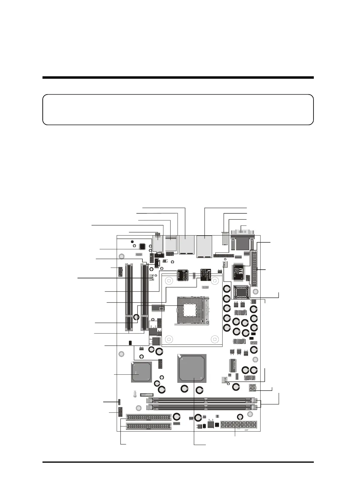
This section outlines how to install and configure your mainboard. Refer to the following
mainboard layout to help you to identify various jumpers, connectors, slots, and ports.
Then follow these steps designed to guide you through a quick and correct installation of
your system.
3.1 Step-by-Step Installation
Accessories Of FB52
JP7
JP6
JP10
USB
USB
SPDIF
JP12
JP2
CD-IN
AUX-IN
CN5
CN11
JP5
JP11
Line-out/MIC
PCI1
PCI2
FAN3
1
1
1
1
1
1
1
1
1
1
1
1
1
1
JP9
1
IDE1
FDD
IDE2
CN6
DIMM1
FAN2
FAN1
JP8
IR
DIMM2
25193Q1 225E
ALC650
C
PS/2 Keyboard/Mouse Connectors
Parallel Port Header - JP9
SPDIF-Out Connector
10/100M LAN & USB 2.0 Connectors
AUX_IN -CN11
5.1 Channel Audio Connectors
FAN1
IR Header-JP8
Two PCI Slots
Wireless KB and MS - JP5Header
SPDIF_In - JP10Header
Clear CMOS - JP2
Front-Panel Headers
- JP12
Extended USB 2.0
Headers - JP6/JP7
Two 184-pin DDR-SDRAM DIMM Sockets
One Floppy Connector
ITE8712F
ATX Power Connector-CN7
FAN2
SOCKET 478
FAN3
Audio Cotroller
(Realtek ALC650)
Line-out/MIC Header-JP11
CD_IN-CN5
ATX +12V Power Connector - CN6
Intel 82801DB SB
Intel 82551 QM LAN
Controller
Intel 82540 EM LAN
Controller