- 17 -
Step 6
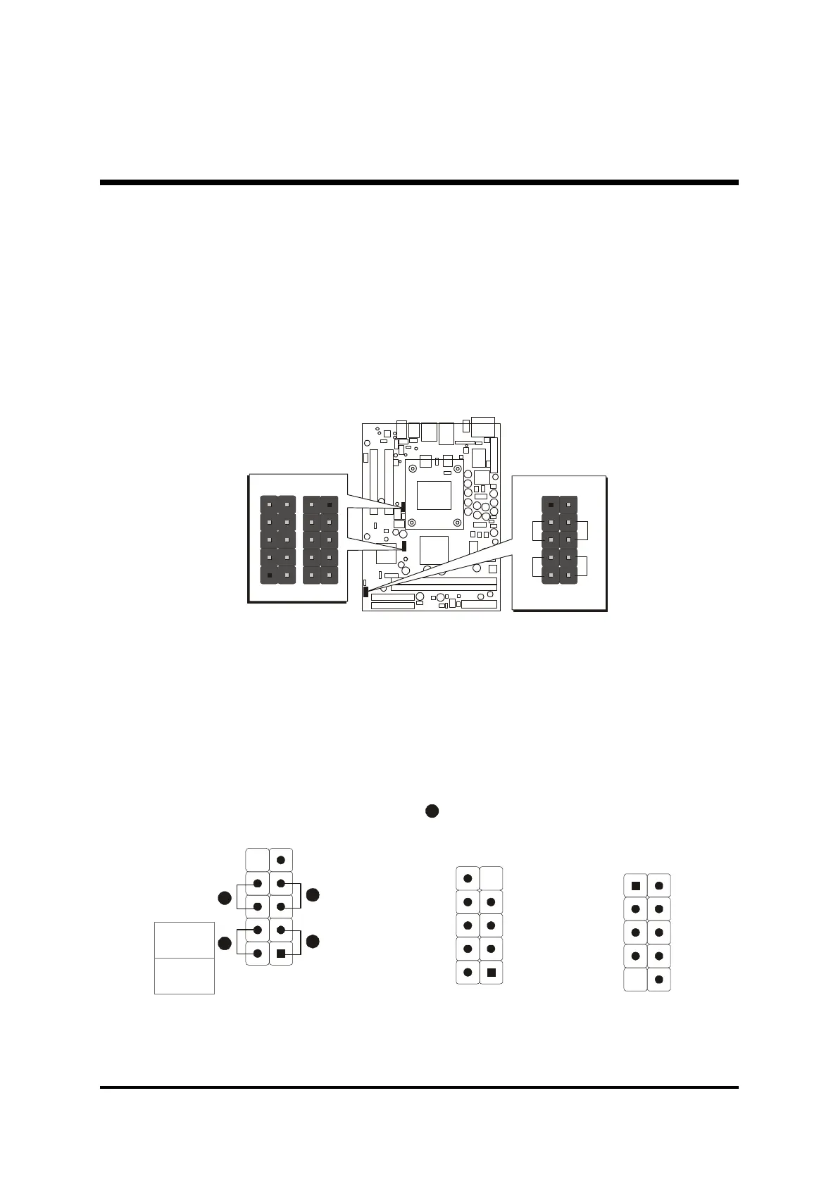
Connect Front Panel Switches/LEDs/Speaker/USB
You can find there are several different cables already existing in the system
case and originatinting from the computer's front-panel devices (HDD LED,
Power LED, Reset Switch, or USB devices etc.) These cables serve to
connect the front-panel switches, LEDs, and USB connectors to the
mainboard's front-panel connectors group (JP6, JP7, JP12), as shown
below.
1. ATX Soft Power On/Off (PWON)
2. HDD-LED (HLED)
3. Green-LED and Power-LED (GLED/PLED)
4. Hardware Reset Switch Button (RST)
5. Extended USB Header
-
+
+
-
RST
HLED
GLED
PLED
PWON
N/A
GND
USBD1+
USBD1-
+5V
+5V
GND
N/A
KEY
GND
USBD0+
USBD0-
+5V
+5V
USBD0-
USBD0+
GND
KEY
1
USB port 2
5
JP6
JP7
USB
1
1