HostHost
Shield
30 31 32 6
30 31 32 6
30 31 32 6
33
34
43
44
6
30 31 32 6
40 41 42 7
40 41 42 7
CDB620-
001
CDB620-
001
CDB620-
001
Device 2 3
Device 3 3
Device 4 3
(Slave) 7
(Slave) 7
(Slave) 7
GN = 01 5
Device 1 3
(Master) 4
GN = 63 5
GN = 02 5
GN = 03 5
(max. 32 participants) à
Stub 8
Switch 2
ON
OFF
S2 (TermCAN):
Switch 2
ON
OFF
S2 (TermCAN):
Switch 2
ON
OFF
S2 (TermCAN):
21 22 23 6
31 32 33 7
CDM420-
0001
Switch 2
ON
OFF
S4 (TermCAN):
CAN_H
CAN_L
Shield
GND
CAN_H
CAN_L
Shield
GND
CAN_H
CAN_L
Shield
GND
CAN_H
CAN_L
Shield
GND
CAN_H
CAN_L
Shield
GND
GND
GND
GND
RxD
TxD
TD‒
RD‒
RD+
TD+
RS-232RS-422
T‒/TxD
R‒/RxD
T+
R+
CDB620-001
42
Connection
cable 9
Connection
cable 9
Connection
cable 9
Connection
cable 9
CAN
CAN
CAN
amongst
others
CAN 6
amongst
others
CAN 6
amongst
others
CAN 6
amongst
others
CAN 6
Switch 2
ON
OFF
S2 (TermCAN):
Serial Host interface 1
Alternative connection module á:
422
485
S6 (RS):
GN = Device number ß
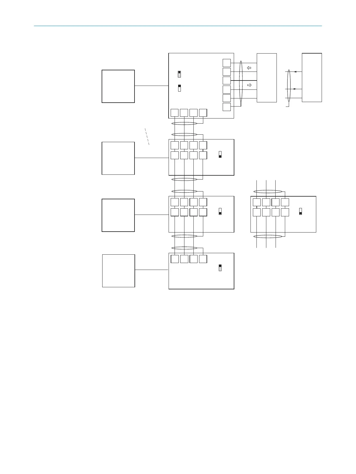
Figure 66: Wire the CAN interface of the device in the CDB620-001 connection module. Connec‐
tion and looping through of the supply voltage and connection of a trigger sensor for read cycle
generation at the master, for example, are disregarded here!
1
Serial host interface
2
Switch
3
Device
4
Master
5
Device number
6
CAN etc.
7
Slave
8
Branch line
9
Connecting cable permanently connected with the device (male connector, D-Sub-HD, 15-
pin)
ß
Device number (GN)
à
Maximum 32 users
á
Example of alternative connection module:
ANNEX 13
8022502/15NT/2020-02-11 | SICK O P E R A T I N G I N S T R U C T I O N S | Lector621
109
Subject to change without notice