Alternative connection module for V2D621x-xxxxxYx (serial variant, Y = D or E):
CDM420-0001 or CDM420-0006.
NOTE
Activate the CAN data interface in the device with a configuration tool, e.g. the configu‐
ration software SOPAS ET.
Make further settings in the device corresponding to the function of the device in the
system configuration.
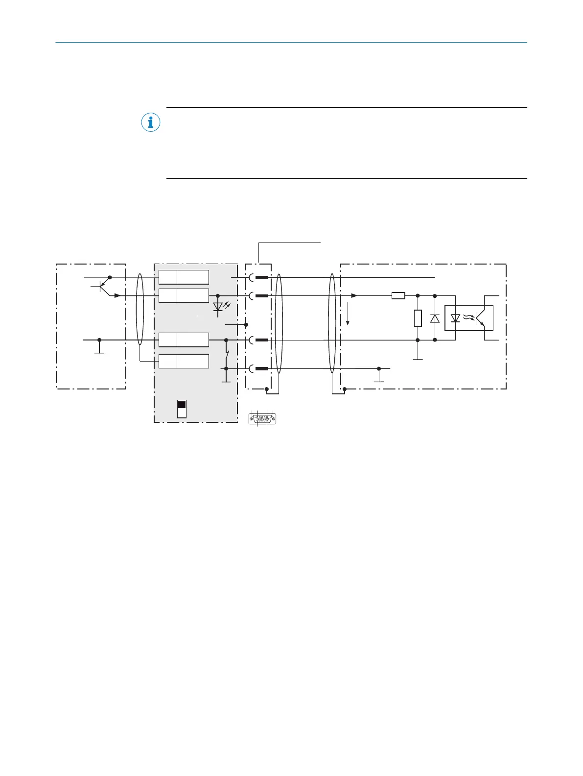
13.6.7 Wiring the digital inputs “Sensor 1” and “Sensor 2” of the device in the CDB620-001
Device = Lector621 ECO = V2D621x-xxxxxYx (serial variant, Y = D or E)
Device
4CDB620-001
V
S
V
S
V
S
GND
GND
SensGND
3.32 K
6.64 K
Sensor D
V
in
C
15
1
5
12
SGND
6
Shield
11
U
IN
*
A
Sens B
Out
U
IN
*
GND
S3
ON
OFF
S3 : SGND-GND
Shield
GND
.
.
.
SensGND
Trigger sensor 1
PNP sensor 7
E.g. photo-electric
switch 6
8
5
110
15
6
11
5
3
Cable 2
Figure 67: Trigger sensor supplied with power by connection module CDB620-001
1
Trigger sensor, e.g., for read cycle generation
2
Connecting cable permanently connected with the device (male connector, D-Sub-HD, 15-pin)
3
Input voltage V
in
4
Device
5
Connection module: female connector, D-Sub-HD, 15-pin
6
e.g. photoelectric sensor
7
PNP sensor
8
Supply voltage V
S
13 ANNEX
110
O P E R A T I N G I N S T R U C T I O N S | Lector621 8022502/15NT/2020-02-11 | SICK
Subject to change without notice