4
Digital input of the device (“Sensor 1” or “Sensor 2”)
5
Input voltage V
in
!... $
For pin assignment, see respective device
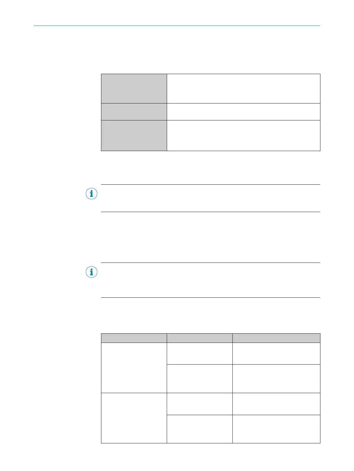
Table 12: Characteristic data of the digital inputs “Sensor 1” and “Sensor 2”
Switching behavior Power to the input starts the assigned function, e.g. start of the
internal reading interval of the device.
Default: active high
Debouncing: 10 ms (standard)
Features
•
Opto-decoupled, reverse polarity protected
•
Can be wired with PNP output of a trigger sensor
Electrical values The electrical values are identical for all digital inputs of the
device.
Low: V
in
1)
≤ 2 V; I
in
2)
≤ 0.3 mA
High: 6 V ≤ V
in
≤ 30 V; 0.7 mA ≤ I
in
≤ 5 mA
1)
Input voltage.
2)
Input current.
Function assignment
NOTE
Assign the functions for the digital inputs in the device using a configuration tool, e.g.
the configuration software SOPAS ET.
Extension: additional logical digital inputs in the device for physical external digital
inputs on the optional connection module
Thanks to the optional CMC600 parameter cloning module in combination with the
CDB or CDM connection module, the two digital inputs “External input 1” and “External
input 2” are additionally available at the relevant terminals of the connection module.
NOTE
The external digital inputs are software-controlled and therefore do not offer the same
timing precision as physical digital inputs. The external digital inputs may not be suit‐
able for time-critical applications.
For the electrical characteristic data of the two external digital inputs, see the respec‐
tive connection diagrams for the connection modules in these operating instructions.
Wiring the digital inputs of the device via a connection module:
Connection modules Digital inputs Reference
CDB650-204 “SENS/IN 1”
“SENS/IN 2”
see "Wiring digital inputs of
the device in the CDB650-204",
page 73
External input 1
(“EXT. IN 1”)
External input 2
(“EXT. IN 2”
see "Wiring the external digital inputs
of the device in the CDB650-204",
page 75
CDM420-0006 “Sensor 1”
“Sensor 2“
see "Wiring digital inputs of the
device in the CDM420-0006",
page 87
External input 1
(“Aux In 1”)
External input 2
(“Aux In 2”)
see "Wiring the external digital inputs
of the device in the CDM420-0006",
page 89
ELECTRICAL INSTALLATION 6
8016185/19E9/2020-10-21 | SICK O P E R A T I N G I N S T R U C T I O N S | Lector64x/65x Flex, Lector65x Dynamic Focus
43
Subject to change without notice