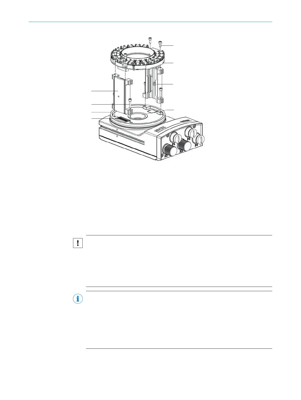
1
Spacer, left with electrical connection
2
4 tapped blind holes, M2.5, 5.5 mm deep, for mounting the spacer
3
4 long screws
4
Electrical connection for the integrated illumination unit
5
4 short screws
6
Integrated illumination unit
7
Spacer, right
8
Light inlet with threaded connection for the lens
Important information
NOTICE
Risk of damage due to electrostatic discharge
Electrostatic discharge from the human body may damage parts of the illumination unit
or the camera housing.
■
Take the necessary ESD precautions when assembling the device.
■
Do not touch the open contacts of the electrical connection on the camera hous‐
ing and the illumination unit.
NOTE
Possible impairment of image quality
Contamination (e.g. dust, fingerprints) on the image sensor can impair the image
quality and decoding performance of the product.
►
Ensure a dust-free and dry environment when mounting components.
►
Do not touch the image sensor in the light inlet opening of the product with your
fingers.
►
Do not touch the glass lenses at either end of the lens unit with your fingers.
4 MOUNTING
20
O P E R A T I N G I N S T R U C T I O N S | Lector85x CAN I/O 8027859/1KN0/2023-08-02 | SICK
Subject to change without notice