Power/CAN
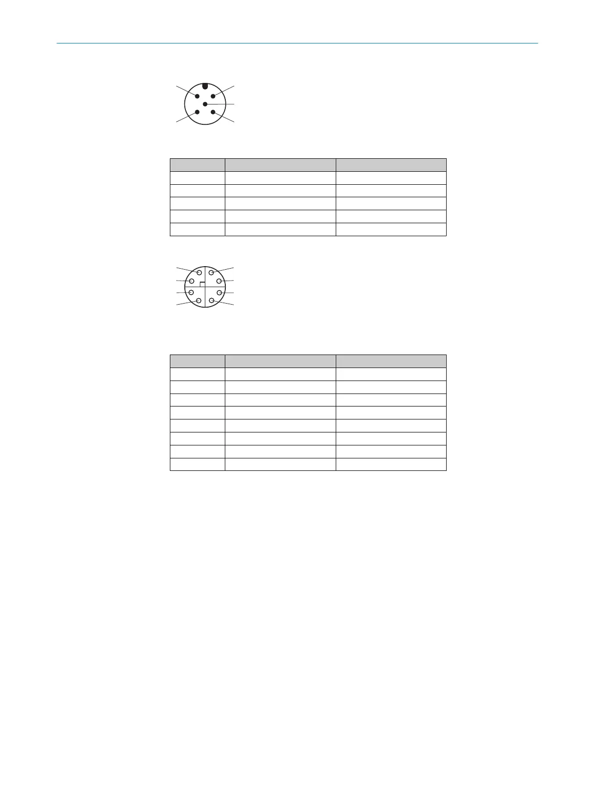
Figure 9: M12 male connector, 5-pin, A-coded
Contact Signal Description
1 – Shielding
2 Vs Supply voltage
3 GND Supply voltage: 0 V
4 CAN H CAN-Bus HIGH (IN/OUT)
5 CAN L CAN-Bus LOW (IN/OUT)
Gigabit Ethernet
Figure 10: Female connector, M12, 8-pin, X-coded
Table 1: Pin assignment for Gigabit Ethernet
Contact Signal Description
1 TRD0_P Sender+/receiver+ 0
2 TRD0_N Sender–/receiver– 0
3 TRD1_P Sender+/Receiver+ 1
4 TRD1_N Sender–/Receiver– 1
5 TRD3_P Sender+/Receiver+ 3
6 TRD3_N Sender–/Receiver– 3
7 TRD2_N Sender–/Receiver– 2
8 TRD2_P Sender+/Receiver+ 2
Complementary information
Pre-assembled cables can be found on the product page.
The call is made via the SICK Product ID: pid.sick.com/{P/N}/{S/N}
{P/N} corresponds to the part number of the product, see type label.
{S/N} corresponds to the serial number of the product, see type label (if indicated).
Further topics
•
Information on interfaces: Technical data
5.3 Network services and ports
Available network services and ports can be viewed in SOPASair under Diagnostics >
Cybersecurity.
5.4 CAN interface
Configuration of the CAN interface
Configure the CAN data interface using SOPASair.
ELECTRICAL INSTALLATION 5
8027859/1KN0/2023-08-02 | SICK O P E R A T I N G I N S T R U C T I O N S | Lector85x CAN I/O
27
Subject to change without notice