4
Grounding point 3
5
Insulated mounting
6
Grounding point 2
7
Ground potential difference
8
Grounding point 1
9
Metal housing
ß
Shielded electrical cable
Even in the event of large differences in the ground potential, ground loops are effec‐
tively prevented. As a result, equalizing currents can no longer flow via the cable shields
and metal housing.
NOTICE
The voltage supply for the device and the connected peripheral devices must also
guarantee the required level of insulation.
Under certain circumstances, a tangible potential can develop between the insulated
metal housings and the local ground potential.
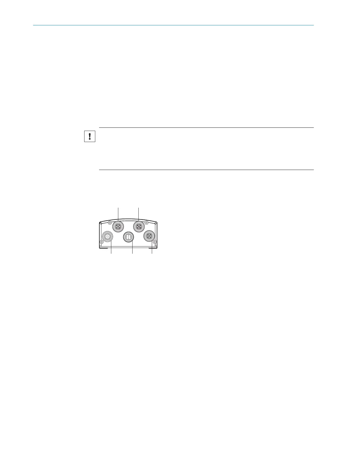
5.2 Pin assignment
Overview
1
P1: Gigabit Ethernet 1
2
P2: Gigabit Ethernet 2
3
P3: Gigabit Ethernet 3
4
X2: Power/CAN
5
X1: Power/CAN/serial interface/IO
Important information
Prerequisites
General
•
Connect the connecting cables in a de-energized state. Do not switch on the sup‐
ply voltage until installation is complete and all connecting cables are connected
to the device and control.
•
Wire cross-sections in the supply cable from the user’s power system must be
implemented in accordance with the applicable standards.
•
In the case of open end cables, make sure that bare wire ends do not touch. Wires
must be properly insulated from each other.
•
The maximum current consumption depends on how the product is used. If out‐
puts are used, the current consumption will be higher. Ensure that the sum of the
output currents at the outputs does not exceed 400mA.
Data cables
•
Use shielded data cables with twisted-pair wires.
•
Implement proper and complete shielding concept.
ELECTRICAL INSTALLATION 5
8027859/1KN0/2023-08-02 | SICK O P E R A T I N G I N S T R U C T I O N S | Lector85x CAN I/O
25
Subject to change without notice

 Loading...


