•
To avoid interference, always use EMC-compliant cables and layouts. This applies,
for example, to cables for switched-mode power supplies, motors, clocked drives,
and contactors.
•
Do not lay cables over long distances in parallel with voltage supply cables and
motor cables in cable ducts.
Voltage supply
•
Configure the circuits connected to the device as ES1 circuits or as SELV circuits
(SELV = Safety Extra Low Voltage). The voltage source meets the requirements of
ES1 (EN62368-1) or SELV (EN60950-1).
•
The device must be supplied with an energy-limited source as per UL61010-1, 3rd
ed. cl. 9.4 or a limited current source as per UL62368-1 or Class 2 as per NEC.
•
Required power output of the voltage source: at least 48W
•
For a supply voltage of DC 24V ±20%, protect the cables with a separate fuse.
The type of fuse required depends on the cable used (typically e.g. cable M12
17-pin with 2A fuse, cable M12 5-pin with 4A fuse). Install the fuse in the supply
circuit at the start of the supply cable.
•
To ensure protection against short-circuits/overload in the customer’s supply
cables, choose and implement wire cross-sections in accordance with the appli‐
cable standards.
Power/CAN/serial interface/IO
1
2
6 714
12
3
4
5
8
9
10
11
13
15
17
16
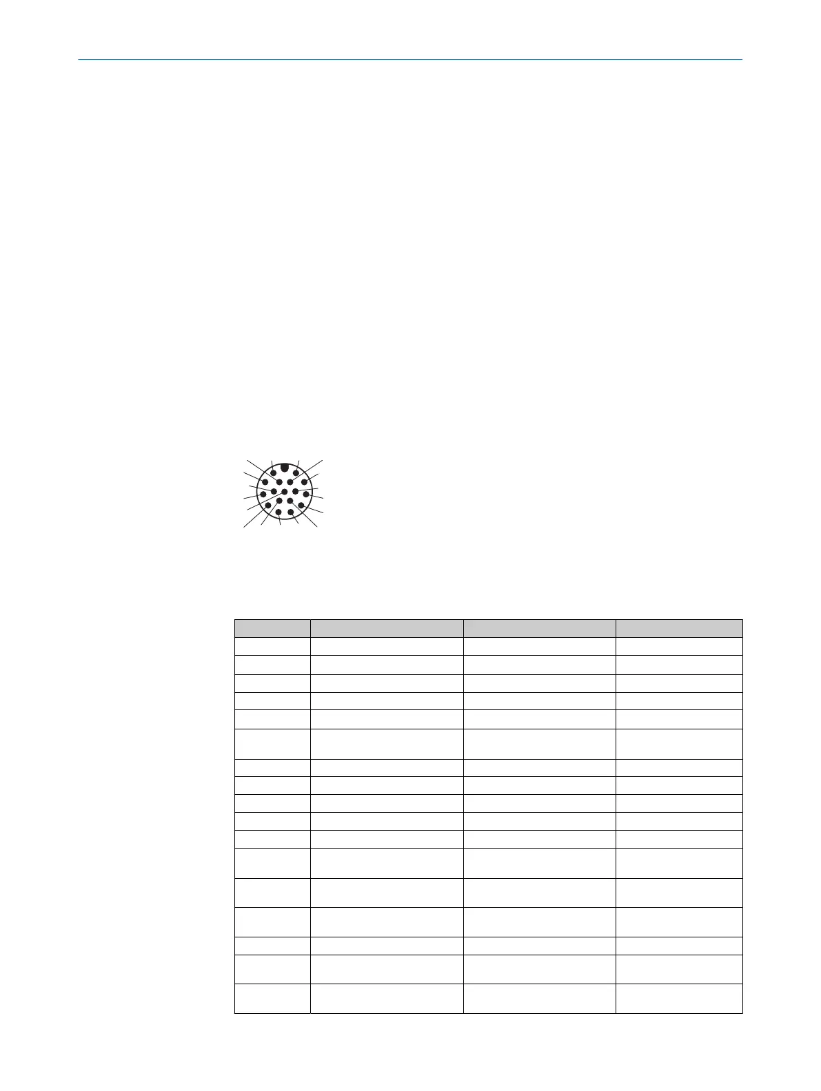
Figure 8: M12 male connector, 17-pin, A-coded
The serial interface and the digital inputs and outputs are not available. Do not connect
the associated pins.
Contact Signal Description Information
1 GND Supply voltage: 0 V
2 V
S
Supply voltage: DC 24V ±20%
3 CAN L CAN-Bus LOW (IN/OUT)
4 CAN H CAN-Bus HIGH (IN/OUT)
5 TD+ (RS-422) Serial data interface (Sender+)
6 TD- (RS-422)
TxD (RS-232)
Serial data interface (Sender–)
7 TxD (RS-232) Serial service interface (Sender) Do not connect.
8 RxD (RS-232) Serial service interface (Receiver) Do not connect.
9 SensGND Digital input ground
10 Sensor 1 Digital input 1
11 RD+ (RS-422) Serial data interface (Receiver+)
12 RD- (RS-422)
RxD (RS-232)
Serial data interface (Receiver–)
13 DIO 3 Configurable digital input and out‐
put 3
Do not connect.
14 DIO 4 Configurable digital input and out‐
put 4
Do not connect.
15 Sensor 2 Digital input 2
16 DIO 5 Configurable digital input and out‐
put 5
Do not connect.
17 DIO 6 Configurable digital input and out‐
put 6
Do not connect.
5 ELECTRICAL INSTALLATION
26
O P E R A T I N G I N S T R U C T I O N S | Lector85x CAN I/O 8027859/1KN0/2023-08-02 | SICK
Subject to change without notice