Operation
MCS300P · Technical Information · 8013265 V1-2 · © SICK AG 29
Subject to change without notice
3.5.3 I/O
Menu: Parameterization/I/O
This menu displays the data interfaces.
3.5.3.1 Addressing system
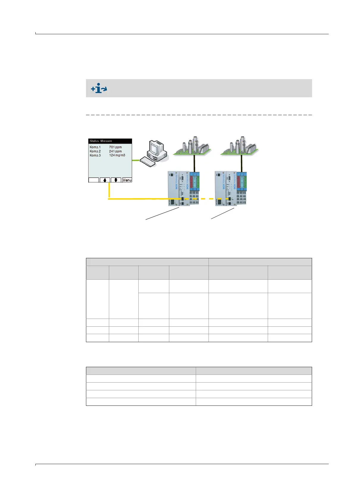
Fig. 3 MCS300P topography
Refer to the System Documentation delivered with your MCS300P for the
hardware installed.
Topography Addressing in MCS300P
Node CAN bus
address
[1]
[1]Set with the address switch on the CAN bus gateway ( Operating Instructions "Modular System
I/O)"
I/O module I/O module
type
[2]
[2]As example
Topographical
addressing
Functional
addressing
N1 0 1 AO02 N1M1AO1(AO02)
N1M1AO2(AO02)
AO1
AO2
2 DI04 N1M2DI1(DI04)
N1M2DI2(DI04)
N1M2DI3(DI04)
N1M2DI4(DI04)
DI1
DI2
DI3
DI4
N2 1 1 AO02 N2M1AO1(AO02) A03
... ... ... ... ... ...
N8 7 ... ... ... ...
Abbreviation Significance
Nx Node (N) = CAN bus gateway.
Mx I/O module (M).
DIx, DOx, AIx, AOx Digital and analog inputs/outputs.
(DIxy), (DOxy), (AIxy), (AOxy), (DI04ISO), (FDxy) I/O module type
CAN bus gateway 1
Node N1
CAN bus address 0
[[1]]
I/O module 1 (M1): AO02
I/O module 2 (M2): DI04
CAN bus gateway 2 ... 7
Node N2 ... N8
CAN bus address 1 ... 7
[[1]]
I/O module 1 etc.
MCS300P