3.3 Operating principle
3.3.1 Principle of operation
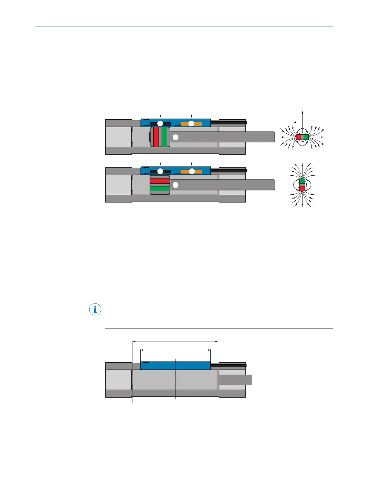
The MPS-G determines the position of an encoder magnet via a row of 2 sensor ele‐
ments located in the sensor head.
Axially and diametrically magnetized magnets can be detected since the two sensor ele‐
ments measure the field strength in both the X- and Y-direction.
y y
xx
y y
xx
1
2
3
1
2
4
m
m
y (radial)
x (axial)
1
Sensor element 1
2
Sensor element 2
3
Axially magnetized magnet
4
Diametrically magnetized magnet
3.3.2 Detection range
The sensor is designed for a detection range of 50 mm. The zero point / physical zero
position is mar
ked with arrows on the sensor head and is located roughly at the center
point of the sensor. From the zero point, -25 mm are measured to the cable and
+25 mm to the fixing screw.
NOTE
The ma
ximum detection range is 60 mm. The actual detection range can vary and
depends on the drive.
50 (1.97)
25.3 (1.00)
0
- 25 (0.98)+ 25 (0.98)
1
2
3
Figure 4: Detection range
1
Detection range
2
Housing length
3
Zero point / Physical zero position
PRODUCT DESCRIPTION 3
8025942/2020-07-16 | SICK O P E R A T I N G I N S T R U C T I O N S | MPS-G with 2 / 3 switching points and IO-Link (up to 16 switching points)
11
Subject to change without notice

 Loading...


