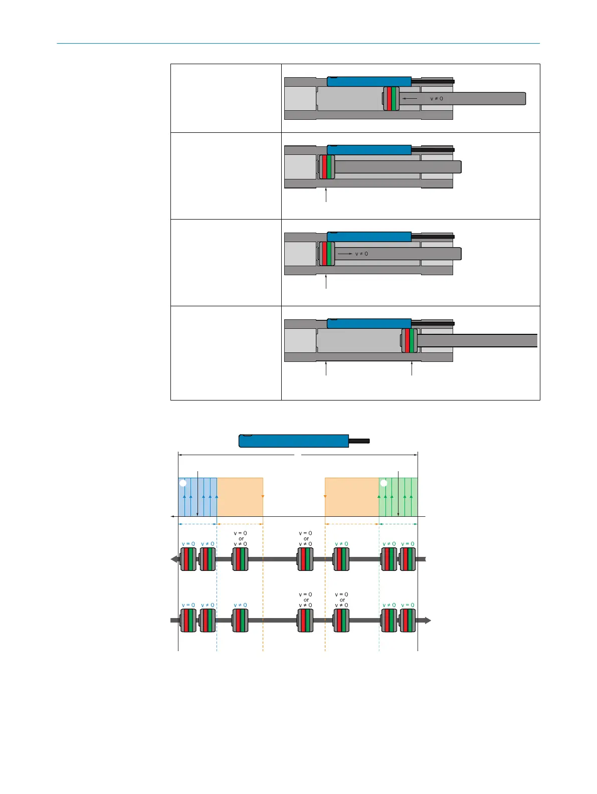
2.) Movement in the direc‐
tion of t
he sensor fixing
screw
3.) First stop: First position
is defined for switching
point
4.) Movement in the direc‐
tion of t
he cable side
5.) Second stop: Second
position f
or switching point
and arrangement of Qint2
(see fixing screw) and
Qint1 (cable set) are
defined
1. Stop:
Qint 2
2. S
top:
Qint 1
v = 0
Switching behavior after Dynamic
Teach of 2 switching points is the following during oper‐
ation:
ON ON
Qint2 Qint1
OFF OFF
Qint2
ON
Qint
OFF
Qint
OFF
Qint
OFF
Qint1
ON
Qint1
ON
Qint1
ON
Qint2
O
N
Qint2
ON
Qint2
ON
Qint
OFF
Qint
OFF
Qint
OFF
Qint1
ON
1
2 3 23
7
8
8
4 6
1
Max. range of movement of drive
2
Tolerance
3
Hysteresis
4
Requirement for Qint2 HIGH:
→ v =0
→ w
it
hin the tolerance
3 PRODUCT DESCRIPTION
14
O P E R A T I N G I N S T R U C T I O N S | MPS-G with 2 / 3 switching points and IO-Link (up to 16 switching points) 8025942/2020-07-16 | SICK
Subject to change without notice

 Loading...


