25,3
11,15
L1
1
2
37,8
L = 300
345
3,8
2,9
6
3,6
2,9
7
15,9
9,1
M12 x 1
40 - 50
8
Pin 4
Pin 1 Pin 2
Pin 3
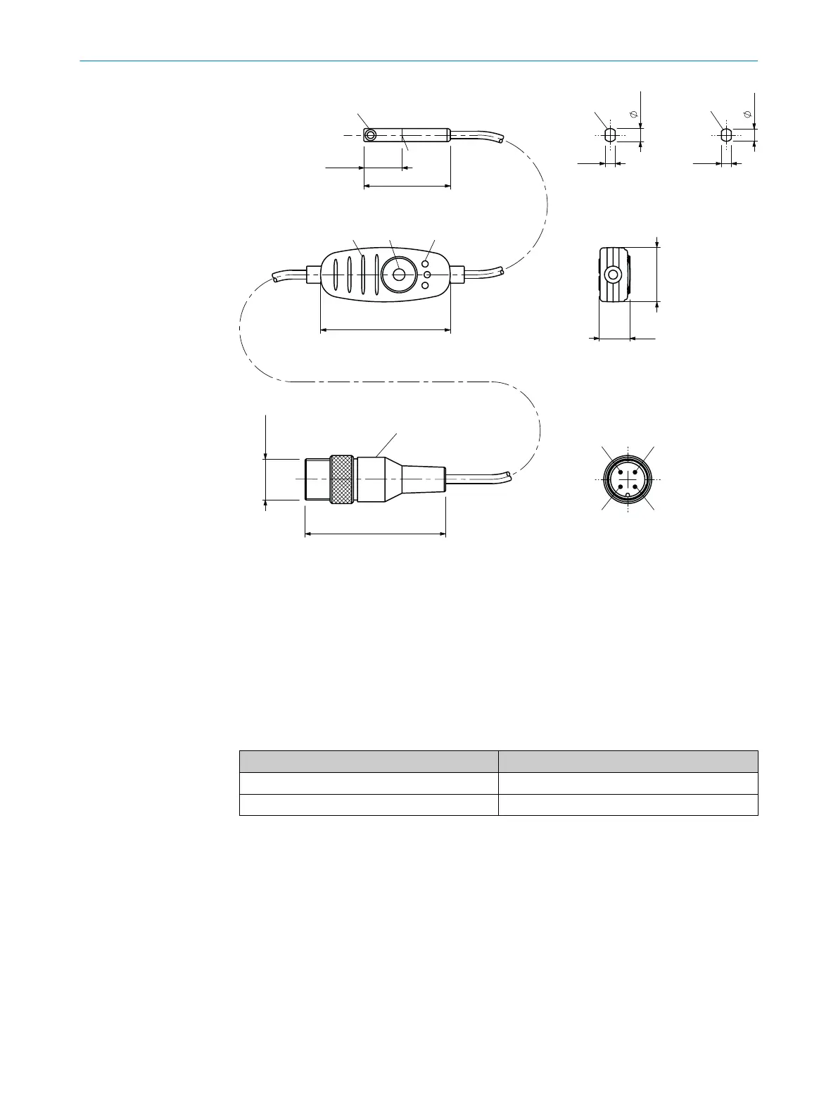
Figure 14: Dimensional drawing with male connector, M12 knurled
1
Center sensor element
2
Fixing screw, size 1.3
3
LED indicator
4
Teach-in button
5
Ribs for cable tie
6
For SMC, Schunk, PHD, Bimba slot (MPS-G50CS...)
7
For Festo-, Zimmer slot (MPS-G50CF...)
8
Connection
Table 13: L1 length of sensor head / control panel connection cable
Type code Connection cable length
MPS-Gxxxxx1xxxxxxxxxxxxxxxxxxx 0.1 m
MPS-Gxxxxx5xxxxxxxxxxxxxxxxxxx 0.5 m
TECHNICAL DATA 13
8025942/2020-07-16 | SICK O P E R A T I N G I N S T R U C T I O N S | MPS-G with 2 / 3 switching points and IO-Link (up to 16 switching points)
43
Subject to change without notice

 Loading...


